Multiple Simple Beam Analysis & Design
Module Summary
- Analyzes and designs up to 12 different non-composite beams within a single calculation item
- Permits wood, steel, and concrete beams
- Permits cantilevers to be modeled at one end or both ends
- Includes full wood and rolled steel section databases
- Allows fixed or pinned support conditions
- Incorporates point loads, concentrated moments, full-length uniform loads, partial-length uniform loads, and trapezoidal loads
- Includes option to perform automatic unbalanced live load placement (skip-loading)
- Incorporates either ASD or LRFD design methodology
- Offers the convenience of fill-in-the-blanks style forms and instantaneous recalculation to facilitate the evaluation of “what-if” scenarios
- Provides highly efficient results summaries as well as generous detail in the on-screen and printed results
- Provides sketch graphics to verify dimensions and load placement – including rich, 3D graphics that support zoom, pan, and many customizable view options.
- Provides shear, moment and deflection diagrams for all load cases
Working view of the Multiple Simple Beam module
Numerical Inputs and Selections
The Multiple Simple Beam module provides input / selection options for general info, point and distributed loads, span loads, distributed loads, and load combinations. Additional material selections are also provided, including 1 click bracing selections.


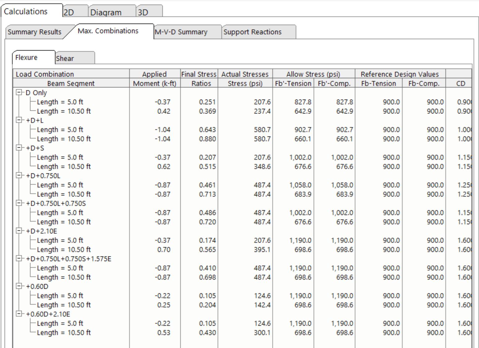
Numerical Output
Numerical output from the multiple simple beam module includes summary results, maximum combinations (flexure and shear), M-V-D summary, and support reactions.


Graphical Output
The Multiple Simple Beam module provides 3 distinct types of graphical outputs:
-
- A 2D “sketch” with options to display all or specific load cases.
- Moment / Shear / Deflection diagrams
- A 3D representation of the beam that you can rotate and optionally display/hide dimensions, supports, axis, loads, and bracing.


Reporting – Convey the effort and thought behind your design
Reporting from the multiple simple beam module provides the detail you need to discuss your plan with clients, plan check agencies, and others.
Granular control over your reports
The Multiple Simple Beam module allows you the option of including (or suppressing) load combinations, deflections, reactions, section properties, and/or stress diagrams from your printout.

