Structural Engineering Calculation Software
Composite Steel Beam Analysis & Design
Module Summary
-
Analyze and design individual composite steel beams using ASD or LRFD design methodologies
-
Choose from the full AISC steel section database for I-shaped beams and a metal deck database which contains profiles from several popular deck manufacturers
-
Add point loads, concentrated moments, uniform loads, and trapezoidal loads
-
Control the timing of the load application with respect to the concrete curing period
-
Specify max allowable deflection ratios for pre-composite, transient, and final load conditions
-
Report as much (or as little) detail as you like with highly efficient result summaries and generous detail in the on-screen and printed results
-
Review and verify dimensions and load placement with 2D sketches and 3D graphics
-
Evaluate beam demands and deflected shapes with detailed shear, moment, and deflection diagrams for all load cases
Working view of the Composite Steel Beam module
Consistent with all ENERCALC modules, inputs are on the left, while graphics and numerical results are displayed on the right.
Numerical Inputs and Selections
The Composite Steel Beam module provides input / selection options for general, span and section data, span loads, and load combinations.


Graphical Output
The Composite Steel Beam module provides 3 distinct types of graphical outputs:
-
- A 2D “sketch” with options to view span & loads or a cross-section, with load cases.
- Moment / Shear / Deflection diagrams
- A 3D representation of the beam that you can rotate and optionally display/hide dimensions, supports, axis, slab, and studs.


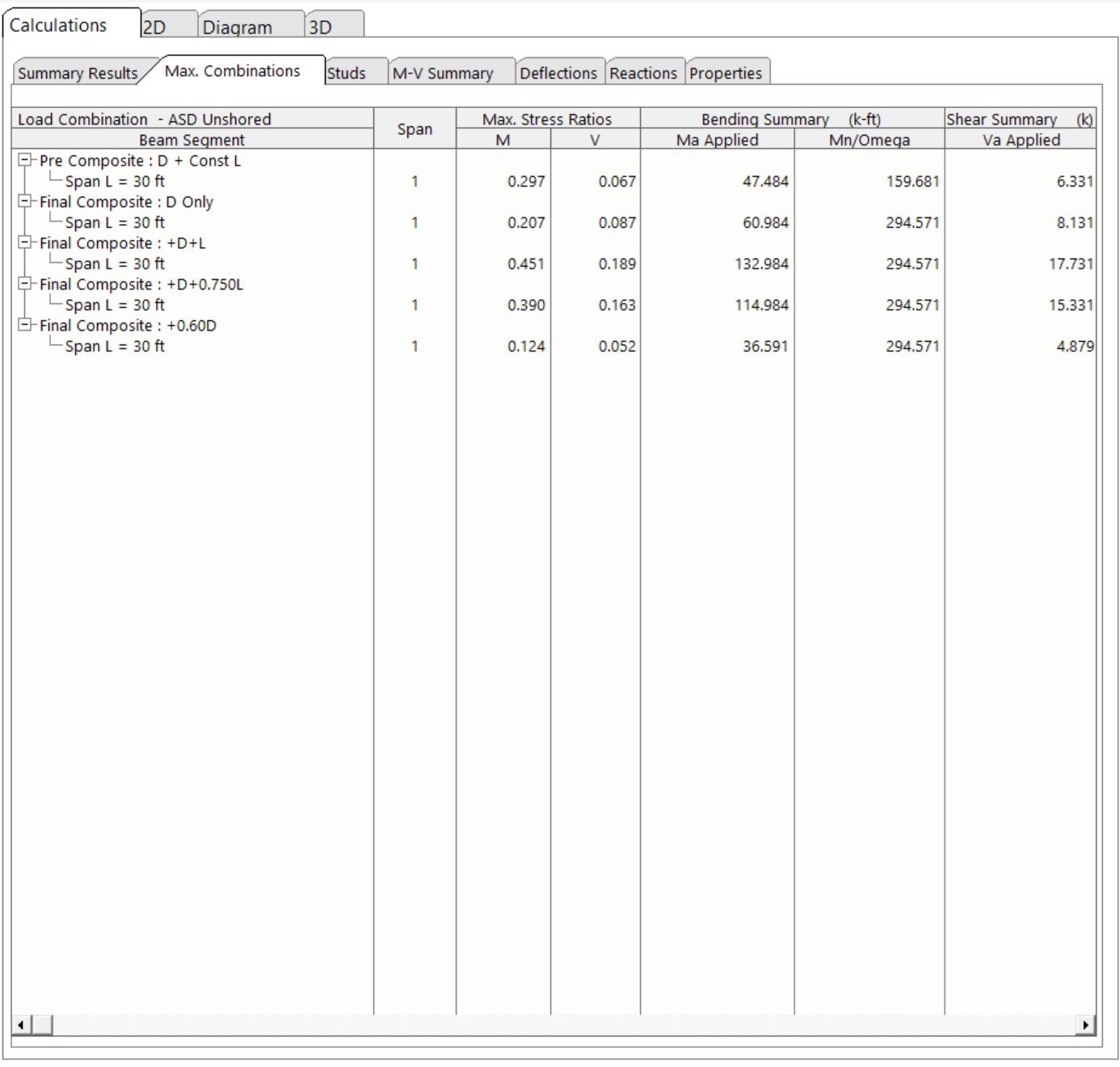
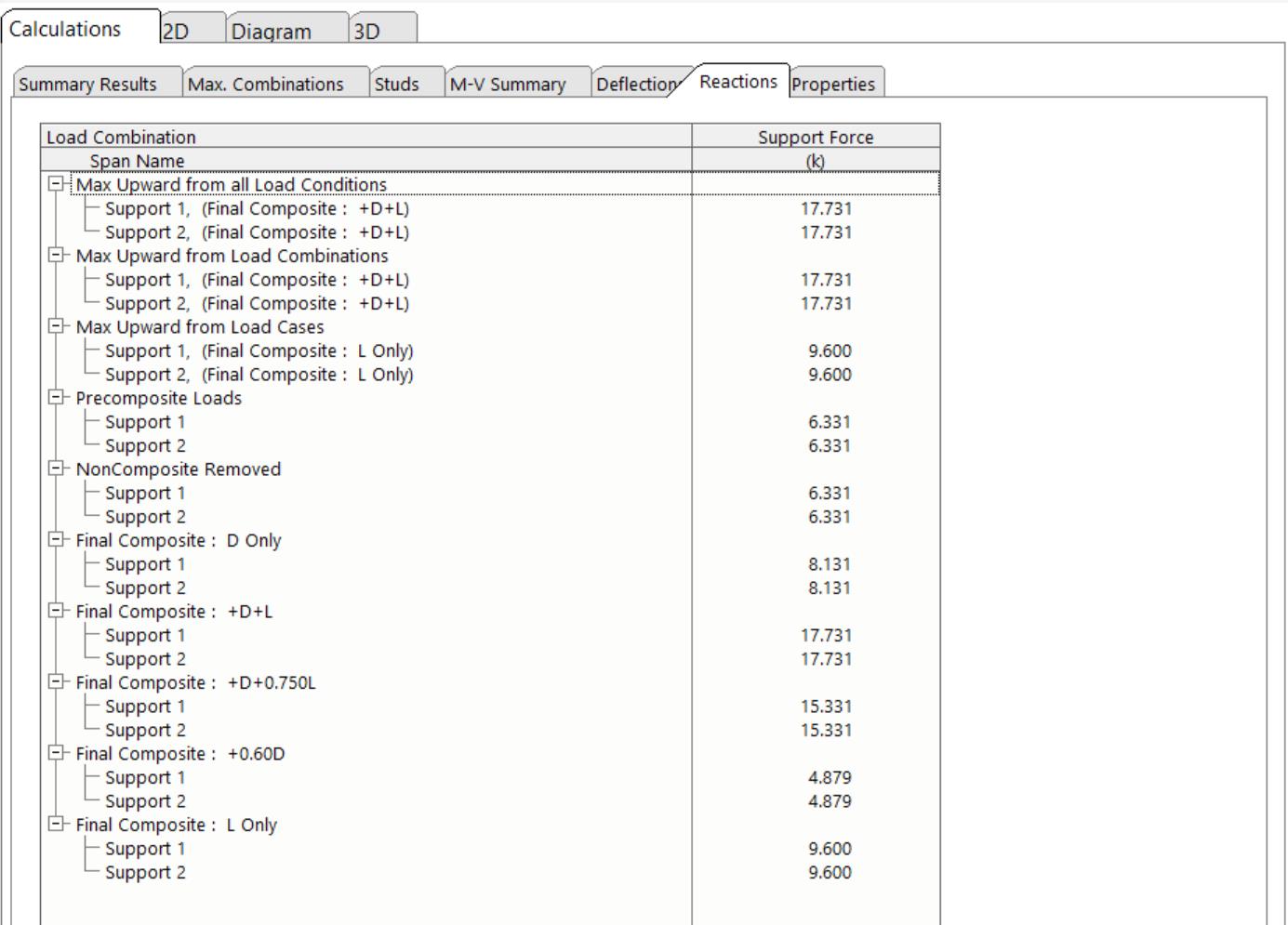
Numerical Output
Numerical output from the composite steel beam module includes summary results, maximum combinations, studs, M-V summary, deflections, reactions, and properties.


Reporting – Convey the effort and thought behind your design
Reporting from the composite steel beam module provides the detail you need to discuss your plan with clients, plan check agencies, and others.
Granular control over your reports
The Composite Steel Beam allows you the option of including (or suppressing) load combinations, deflections, reactions, section properties, and/or stress diagrams from your printout.


