Area Loads |
  
|
Area Loads |
|
Create > Draw Loads > Area Loads prompts you with the following dialog.
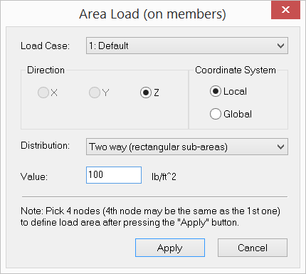
It allows you to assign area loads to enclosed areas of members in the model. You must select a load case to which the area loads belong. Area loads may be specified in either the local or global coordinate system. Global area loads may be in the global X, Y, or Z direction. Local area loads may only be in the local z direction, which is perpendicular to the load area.
A load area is defined by specifying three or four coplanar nodes. The area load is then distributed as line loads to perimeter members of enclosed areas within the load area prior to static or dynamic solution. Various area load distribution methods are available. It is recommended that area loads be defined in their own load cases. In this way, you will find it easier to identify, edit, and delete area loads later on.
The program also allows you to convert area loads to line loads automatically. This feature lets you see how the program would convert the area loads prior to the solution. For more information on the load conversion, see Tables > Area Loads.
 <
<