This module designs steel columns that are subject to axial loads and lateral bending loads about both axes.
The user can select ASD or LRFD methods and has access to a complete database of steel section sizes.
All calculations are according to AISC 360.
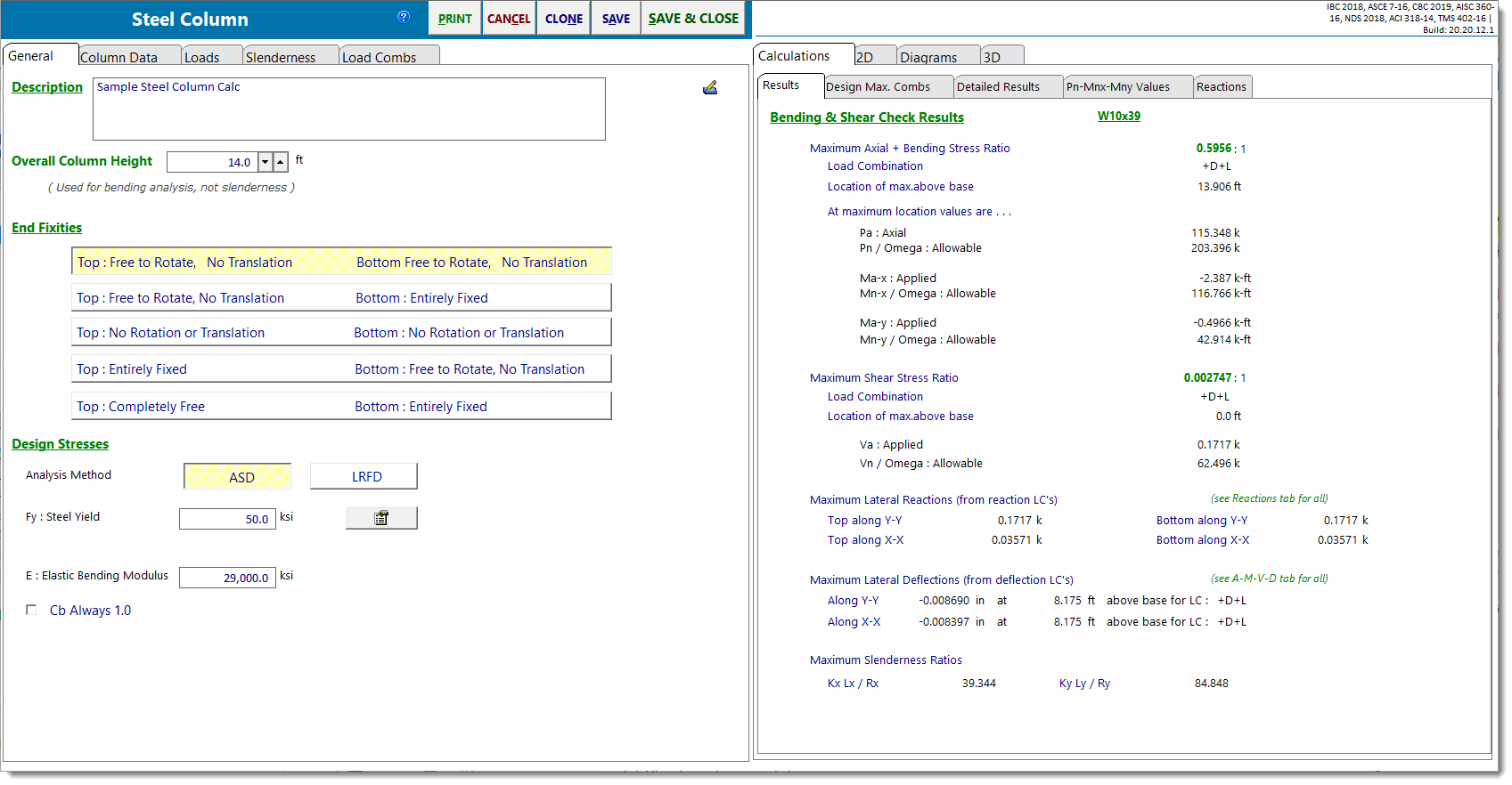
The screen capture below shows the full screen for steel column design. See items below for descriptions of items that are specific to the steel column design module.
For general description of the module, end fixity, loads, and load combinations click here. For slenderness description click here.
General
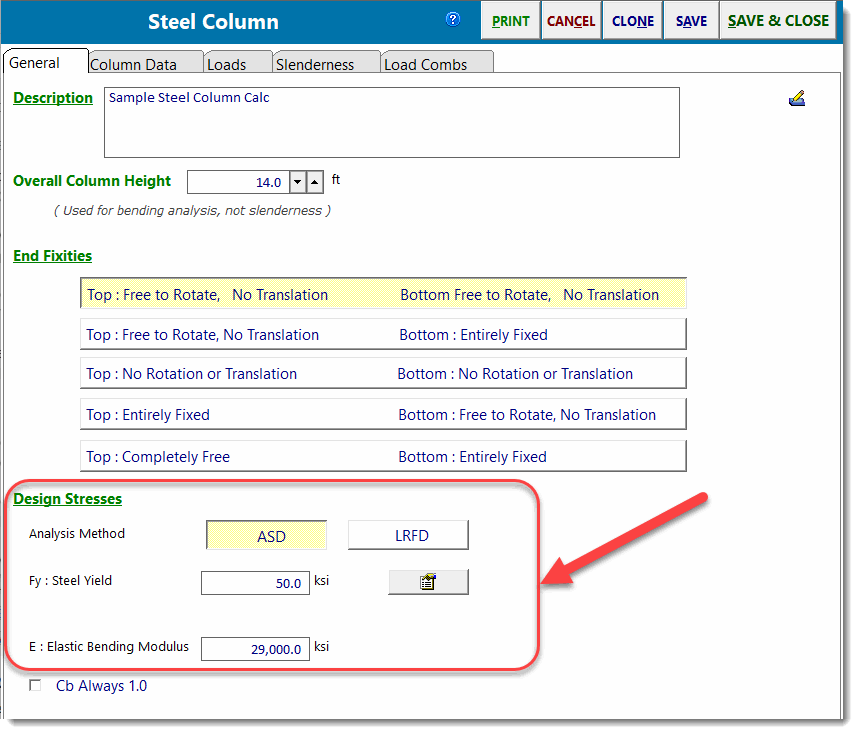
The area indicated in the screen capture below is specific to the steel column selection. Here you can specify ASD or LRFD design procedure and specify the yield strength and elastic modulus of the steel member to be used.
Click the ![]() button to display the Steel Fy Selections dialog to select a standard grade.
button to display the Steel Fy Selections dialog to select a standard grade.
Column Data
All items on this tab are specific to a steel column.
The item circled in red is where you can type in the typical section name, press [Tab], and the section will be searched and retrieved from the built-in database. Or you can click the ![]() button, and you can select a section from the built-in AISC database.
button, and you can select a section from the built-in AISC database.
The items circled in blue are the section properties for the section you have chosen.
The item circled in green is the Quick-List". Click on one of the many buttons with a section letter and the full list of those sections will be displayed to the right. Simply click on a section and it will be assigned to the red and blue areas.
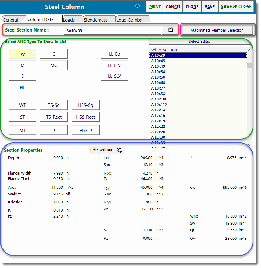
The button circled in pink will display the Steel Member Design dialog (see below).
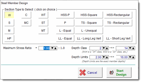
This tool checks all of the steel sections for the selected type (W is selected in this case). A section will be judged to pass if the maximum stress ratio entered is not exceeded
and the depth measurements and depth class are not exceeded.
The term "Depth Class" refers to the nominal dimension of the family to which the section belongs (ex: W14). It does not refer to the actual depth of the section. All sections starting with "W14" are of the "14" depth class.
Results
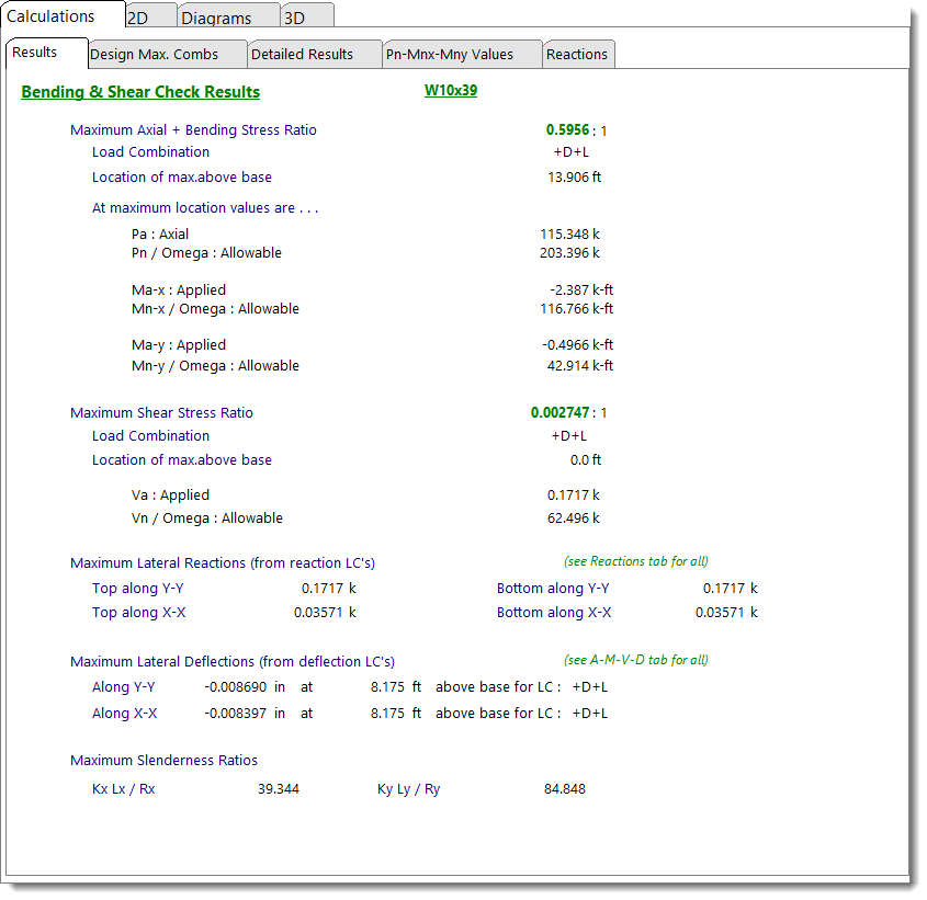
This tab provides a summary of the stress ratios, reactions and deflections for the column.
Max Axial + Bending Stress Ratio is the governing load combination for the column. Listed is the governing load load combination, the AISC formulas that are used, and the location of the maximum stress ratio above the base of the column. Please note that the maximum stress ratio is being reported (along with its location) because it governs the overall design, even though it may not necessarily be the highest axial stress or the highest bending stress experienced anywhere in the column.
Max Shear Stress Ratio will probably never govern for a normally loaded column design. But it is presented here with the governing load combination, location and allowable/actual stress values.
Lateral Load Reactions and Deflections are the result of applied lateral loads.
Design Maximum Combinations
This tab lists the resulting maximum stress ratios for each load combination. This list is created by examining the detailed list (on the next tab) and determining the governing stress ratios for each load combination.

Detailed Results - Shears & Moments
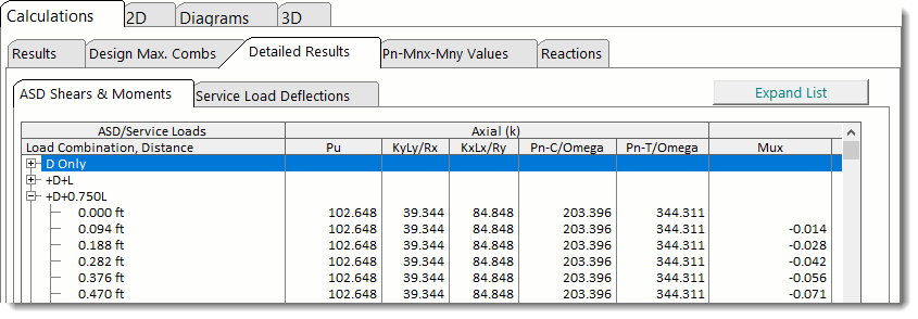
This tab lists the detailed results at small increments along the height of the column, for each load combination.
For consistency, all of the column headings are taken directly from AISC.
Note! This list scrolls to the right to display more information.
Detailed Results - Service Load Deflections
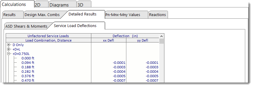
This tab reports the deflections at incremental locations along the height of the column, for each service load condition (i.e. for individual load cases and for a set of built-in service load combinations), along each axis.
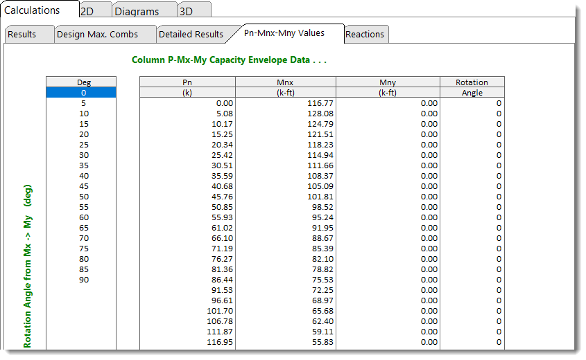
Pn - Mnx - Mny Values
This tab provides capacity envelope data.
Reactions
This tab provides the lateral (non-axial) reactions for individual load cases and for a set of built-in service load combinations, along each axis.

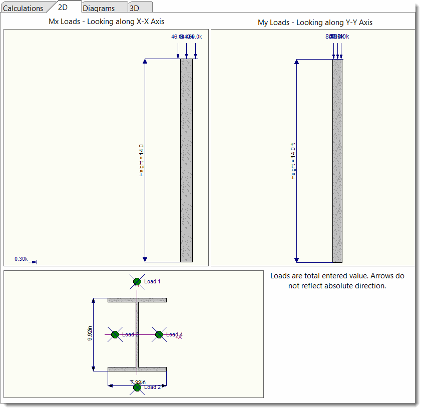
2D Sketch
Diagrams (Axial-Shear-Moment-Deflection)
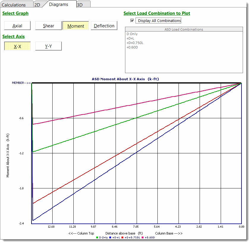
This tab provides comprehensive charting capability to view graphs of Axial load, Shear, Moment, and Deflection along the length of the member. Note that the graphs are oriented such that the right end of the graph represents the column base, and the left end of the graph represents the column top. This was done to maximize the scale of the graph based on the screen area available.
3D Rendering
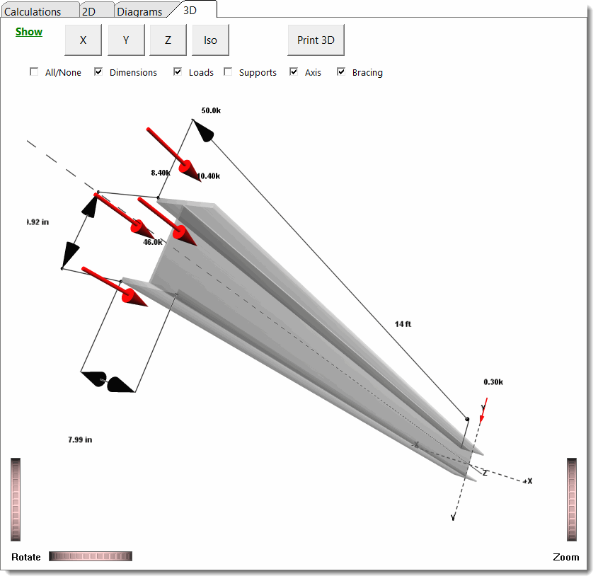
This tab displays the 3D rendering of the column and offers various display options.
