Column Slenderness |
  
|
Column Slenderness |
|
The Slenderness tab allows you to specify the column bracing, which will be considered in axial capacity calculations.
In most of the column modules there are two tabs: "Buckling ABOUT X-X" and "Buckling ABOUT Y-Y". Let's start with the all-important definition of the axis reference for slenderness. Note that the nomenclature used to define column slenderness was updated in May 2023 to bring ENERCALC in concert with the way the industry defines column buckling. Prior to May 2023, ENERCALC used definitions that referred to "buckling IN THE DIRECTION OF" an axis. After the change made in May 2023, ENERCALC uses definitions that refer to "buckling ABOUT" an axis.
Buckling failure of a column can be thought of as an uncontrolled and excessive deflection about a particular axis. When defining slenderness, one of the important values is the distance between points that brace the column against buckling about a particular axis.
The column modules ask you to specify the distance between points of bracing that prevent column buckling about the member's local X-X or Y-Y axis.
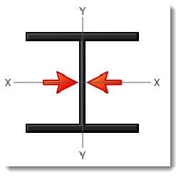
(The X-X axis is always parallel to the "width" dimension of the column. The Y-Y axis is always parallel to the "depth" dimension of the column.)
In addition to preventing column buckling about an axis, any brace that is defined in the column modules will ALSO be interpreted as a brace that stabilizes the compression flange of the column against lateral torsional buckling in the flexural design. Here's where things get fun. When we define the spacing of bracing that is effective in resisting column buckling about the Y axis, that bracing is in place to prevent the column from translating in the X axis direction, like this:
In the screen capture immediately below, we have selected [Fully braced "X" Axis]. This means that the column is fully braced against buckling about its X-X axis, which is parallel to the width dimension.
All materials, column fully braced
This selection sets the column as fully braced, and no slenderness effects will be evaluated.
All materials, typical simple slenderness specification
This selection allows you to enter the unbraced length to use for the column slenderness calculation. Also available are selections for the typical effective length multipliers ("K" factors) for various end conditions.
Note! End fixity is specified on a different tab in the column modules. These slenderness factors do not alter the end fixity you specified for the column, nor do they get determined automatically by the end fixities that you specified.
All materials, typical slenderness with user-defined effective length factor "K"
This selection allows you to enter the unbraced height and the effective length factor "K" to use for the column slenderness calculation.
Note! End fixity is specified on a different tab in the column modules. These slenderness factors do not alter the end fixity you specified for the column, nor do they get determined automatically by the end fixities that you specified.
All Materials, non-sway slenderness calculation by calculating K based on stiffness of adjacent members
There is also an option to Compute K using adjacent members. This advanced selection lets you select the framing condition above and below the column, and using the entered lengths and EI values, it will use standard equations for Non-Sway columns to calculate the effective "K" factor.
Keep in mind that this option is used to define the relative stiffnesses of the framing in the plane of buckling that is being considered. For example, when using the X-X Axis Column Slenderness tab, the plane under consideration is the plane in which the column's X-X axis lies.
 <
<