Columns |
  
|
Columns |
|
ENERCALC SEL has a single basic column design module that supports Wood, Steel, Concrete and Masonry material types.
There are some portions of the graphical user interface that remain consistent for all materials, and this topic will focus on those items. For detailed information about each of the material-specific calculation modules, please review the respective topics below.
Note: The Column modules are not intended for the design of tension members. Column modules should not be applied in situations where the member experiences net tension.
General
The screen capture below shows the portions of the General tab that remain constant for all four material types.
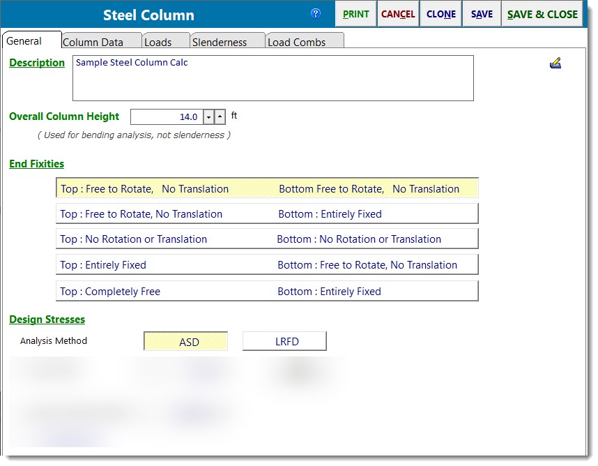
You can easily select a different column material by clicking one of the four material buttons. When you do, the program will load the user interface that is specific to the chosen material.
Overall Column Height is the total height of the column and does not have anything to do with slenderness lengths. This length is used for three things:
•to describe the overall height of the column for the purpose of calculating self weight (if specified),
•to locate the topmost point of load application, and
•to perform the bending analysis when lateral loads are applied.
Rotational End Fixities let you specify how the ends of the columns are or are not attached to boundary conditions. Each condition explicitly describes the translational and rotational boundary conditions at both the top and bottom of the column.
Vertical Loads
Vertical loads can be applied to any location along the height of the column. You use this tab to build a table of applied loads with the [Add], [Copy] and [Delete] buttons.
Include Self Weight option tells the module to automatically calculate the weight of the column and add it as an additional dead load (which will be factored per "D" load combination factor and applied at the top of the column).
Description lets you describe each load you are applying.
Load Eccentricity has "X" and "Y" eccentricity locations so the loads can create Y-Y and X-X axis moments respectively.
Location from Base is where you specify the vertical location of the axial load with respect to the bottom of the column.
Lateral Loads
On this tab you can specify loads that will be applied along the X or Y axes of the column (non-axial loads).
Note! Moments applied at fixed ends have no effect on column design, and will be ignored, producing no effect on the column, and will also NOT appear as reactions.
Applied Load Type & Values has a drop-down list box where you can choose Full Uniform, Partial Uniform, Point Load and Moment load types.
Description lets you describe each load you are applying.
Moment Axis is where you specify about which column axis the load creates its applied moment.
Location from Base is where you specify the vertical location of the lateral load with respect to the bottom of the column.
Load Combination Tab
This tab allows you to specify the load combinations to use for the analysis. The tabs change appearance slightly between ASD and LRFD selections. There are also optional load duration factor entries for wood and masonry design.
Please see the screen captures below for variations based on the selected material.
Steel ASD
Steel LRFD
Concrete LRFD
Wood ASD
Wood LRFD
Masonry ASD
Masonry SD
 <
<