Joint Data |
  
|
Joint Data |
|
Joint Data Tab
This tab is where you add and edit the joints that define the member interconnections for the frame.
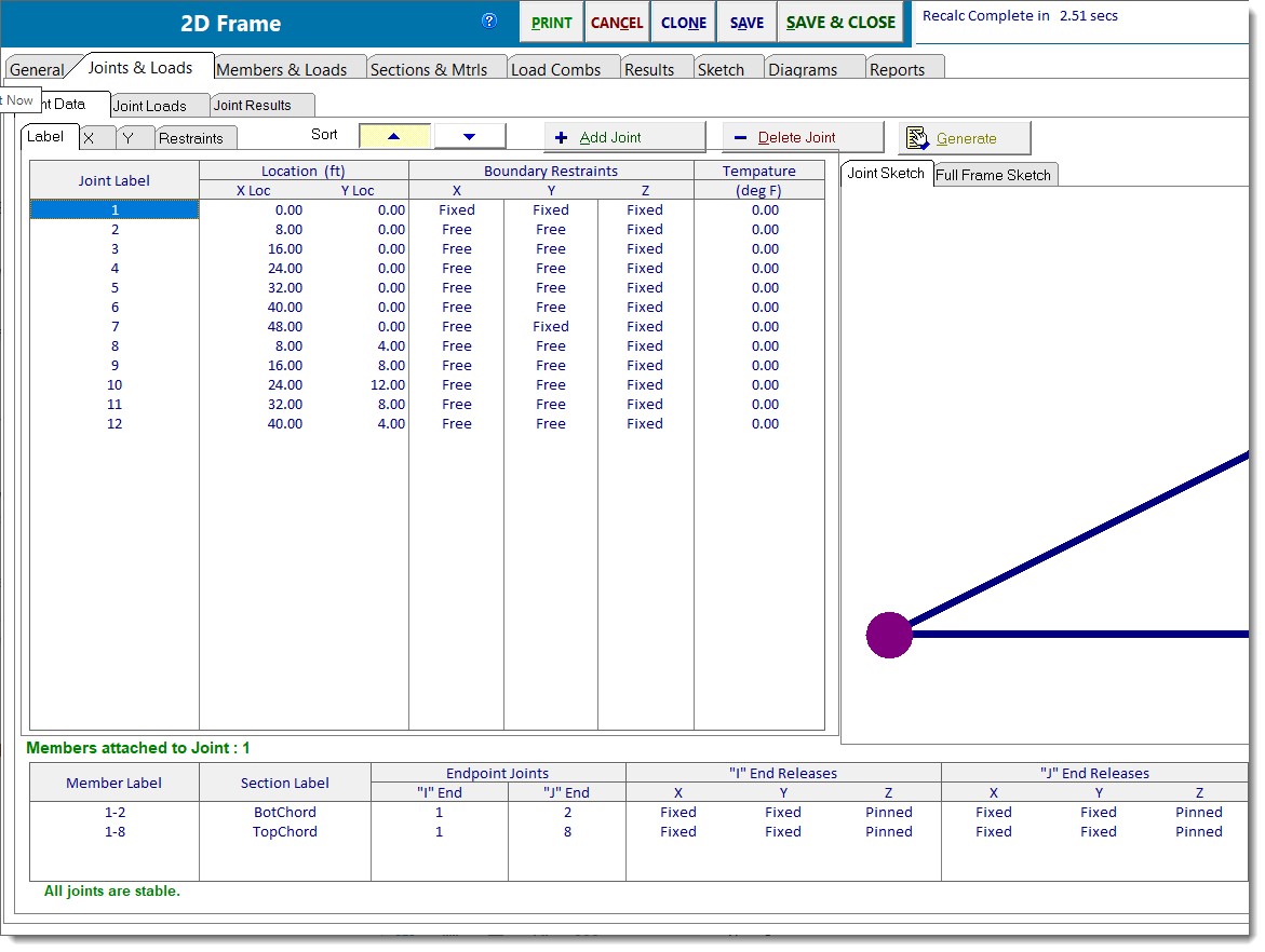
Joint Label
The label for a joint can be up to 25 characters long. They are CASE INSENSITIVE meaning the module internally converts all joint names to all lower case for internal usage.
Location
This is the X and Y location of the joint in a Cartesian coordinate system.
Boundary Restraints
These specify how the joint is connected to the boundary. The boundary is an infinitely rigid item and is typically a footing. See the Joints & Joint Loads topic for more information.
When you click on these items (or use [Tab] to move between them) the entry turns into a drop-down list box with the available selections.
Temperature
This specifies the base temperature for the joint. It is only used when you are defining temperature loads for the members.
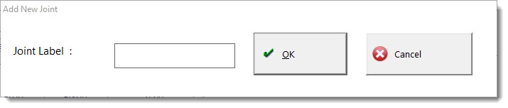
[+Add Joint]
Prompts you for the label to assign to the newly added joint. Joint labels can be up to 25 characters long.
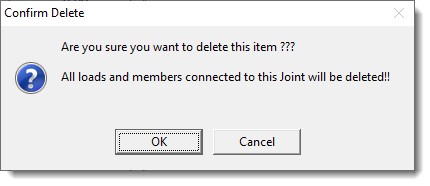
[- Delete Joint]
Deletes the highlighted joint after your confirmation. Keep in mind that members depend upon joints for connectivity. So if there are any members connected to a joint, the members will be deleted if the joint is deleted. Any joint loads that were assigned to a joint will also be deleted if the joint is deleted.
Generate
See bottom of this section.
Joint Sketch/Full Frame Sketch
The Joint Sketch displays a graphic representation of the individual joint that is currently selected in the list of joints along with the member(s) that frame into it. The Full Frame Sketch displays a graphic representation of the entire model with the currently selected joint highlighted for easy recognition.
Editing Joint Information
Click on any data item in the joint list, and the list will switch to an editing mode. See the image below where we have clicked on the "X Loc" for joint 1.
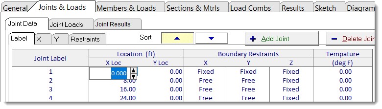
You can type in a numeric value or use the "spin" buttons to change the value by a fixed decimal amount.
To finish the entry either press [Tab], [Enter] or click on another data item in the list.
When your entry is completed the entire frame will be recalculated if the Auto Calculate option is selected.
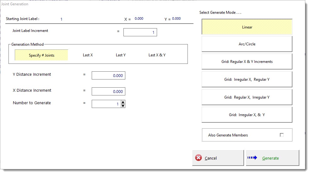
Automatic Joint Generation
You can use the [Generate] button to initiate the automatic generation of joints. Just select from the mode of generation, and you can specify the label and the x and y distance increments to use. The "Grid Irregular X & Y" can generate some very complex joint layouts.
Another powerful tool is the Also Generate Members option, which will generate members to interconnect the joints for the generation grid or arc/circle you have specified.
 <
<