Joints & Joint Loads |
  
|
Joints & Joint Loads |
|
Joints are the points in space where members are interconnected. Members can ONLY connect to another member or the boundary by first connecting to a joint.
IMPORTANT: See JOINT RESTRAINTS below.
Joints & Loads
This tab contains two sub-tabs that allow you to specify joints and loads applied to the joints, and one sub-tab dedicated to the display of results that are relevant to joints.
Note: The data entered into this module is linked by a database system. The effects of this linking can be seen in the screen capture seen below. Notice that the table in the upper half of the view lists available joints for which Joint Data can be viewed. As a result of the data linking, selecting Joint #1 in the upper table automatically causes the lower table to display a list of members connected to Joint #1.
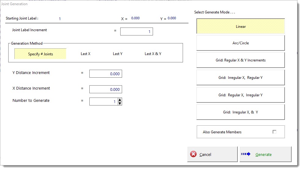
Automatic Joint Generation
You can use the [Generate] button to have joints automatically generated. The joint generation popup is self explanatory....just select from the mode of generation, specify a label increment, the number of joints to generate, and the x and y distance increments to use. The "Grid Irregular X & Y" can generate some very complex joint layouts.
Another powerful tool is the Also Generate Members option, which will generate members to interconnect between the joints for the generation grid or arc/circle you have specified.
Joint Restraints
These interconnections are extremely important, and when set incorrectly, they lead to the majority of the instabilities and other unexpected results when using this 2D Frame module. The connections between members and the connections to the boundary have a significant effect on structural behavior, and as such, they warrant a thorough discussion and complete understanding.
Always keep in mind the following concepts related to joint boundary restraints and the end releases of the member(s) connecting to the joint:
•Joints have Degrees of Freedom (DOF) associated with them.
•In the 2D Frame program, each joint has two translational and one rotational DOF.
•An individual DOF may be restrained or released.
•DOF can be defined as Boundary Restraints or as Member End Releases.
•When the degrees of freedom are defined as Boundary Restraints, they are defined with respect to the global coordinate axis system.
•When the degrees of freedom are defined as Member End Releases, they are defined with respect to the member local coordinate axis system.
The term Degrees of Freedom refers to the capability of a joint to move in the X and Y direction and to rotate about the Z axis.
An X Restraint prevents a joint from moving in the Global X direction.
A Y Restraint prevents a joint from moving in the Global Y direction.
A Z Restraint prevents a joint from rotating about the Global Z axis.
Please see the diagram below for a brief primer on joint restraints and member releases.
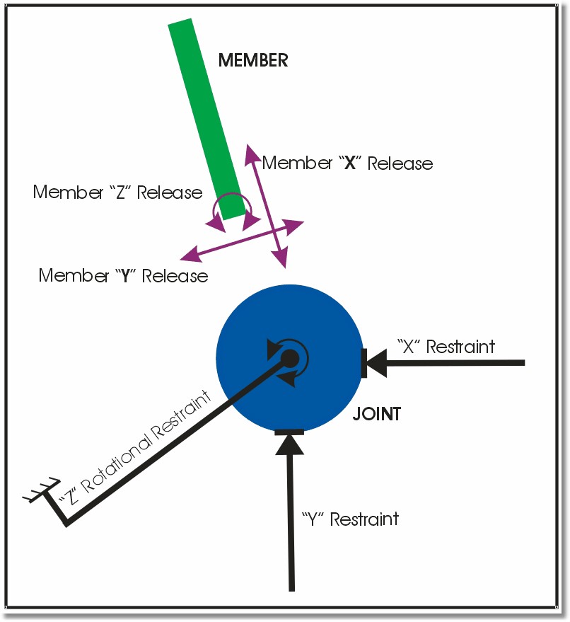
The dark black items define the joint restraints. Joint restraints attach the joint to the boundary. The boundary is an infinitely stiff support and is most commonly a foundation. When a joint is restrained against translation in the X and Y directions and against rotation about the Z axis, it is held firmly in place. Any forces or moments applied to it will result in a reaction which is the boundary applying a force to the joint to keep it from moving in a particular direction.
THE MOST IMPORTANT PIECE OF INFORMATION: Each joint must be prevented from moving in/rotating about each of its three degrees of freedom, either by a joint restraint or by a positive connection to member. If a joint can translate or rotate in an unrestrained manner, then it is unstable.
NEXT MOST IMPORTANT PIECE OF INFORMATION: When a joint restraint is specified, then any connected members that are not released in that particular direction will not deflect in that direction. If a joint has an "X" restraint and a member framing into that joint does not have an "X" release, then the member is actually rigidly connected to the boundary through the joint.
ALSO IMPORTANT: When you are modeling a frame, nearly all joints will be free from the boundary. This means that those joints will need to have their X, Y & Z degrees of freedom restrained by a connection to one or more members. Because members can only attach to each other through a joint, this is usually handled by virtue of the member having all three degrees of freedom "fixed" at its ends. BUT FOR TRUSS CONNECTIONS, THIS CAN CAUSE PROBLEMS WITH THE "Z" rotational degree of freedom. For truss models (where moments are not applied to nodes), it may be easier to achieve stability for all joints by declaring all joints as "fixed" against rotation about the Z-axis, and then "pinning" both ends of all members to prevent the transfer of moment from one member to another.
 <
<