Member Data |
  
|
Member Data |
|
Member Data
Members always span between two joints. The Member End Conditions tell the module how each of the three degrees of freedom at each end of the member are attached to the joint. To connect two members rigidly together you must specify the two connecting ends as "fixed" conditions for all three degrees of freedom. That locks each beam end to the joint.
For each member you can specify the section to use for its properties, and values to be used when stress analysis is performed (unbraced length, slenderness factor, Cm and Cb).
You can also set the member to be inactive to test force distributions and stresses for alternate framing conditions.
Editing Member Information
Click on any data item in the member list, and the list will switch into an editing mode. See the image below where we have clicked on the "X" degree of freedom for the I: end of member 1-2.
You can type in a numeric value or use the "spin" buttons to change the value by a fixed decimal amount.
To finish the entry, either press [Tab], [Enter] or click on another data item in the list.
Note: Each column in the Member Data table can have its own type of editing mode. The Active column turns into a checkbox for yes/no selections. The Section Name column turns into a button so you can select or add a section from the Section list. See descriptions for each item below.
Adding & Deleting Members
To add a member click the [Add Member] button. You will be prompted for three pieces of information:
1) A label for the member.
2) The member's "I" joint number.
3) The member's "J" joint number.
In the screen capture below you will notice a button to the right of the joint label entries. Just click in the "I" or "J" joint entry and click the [Lookup Joints] button  . This will display a window where you can scroll through the list of created joints and select one. Simply click on one of the listed joints and then click [Select].
To delete a member, select the member and click [Delete Member]. After you approve the deletion, that member and all loads applied to that member will be deleted.
Generating Members
You can use the [Generate] button to initiate the automatic generation of members. This is a simple process that automates member creation by generating members between existing nodes in the specified order.
Note: This tool will generate new members, but it will not generate new nodes.
Detailed Item Descriptions (see 2 screen captures below)
Member Label
This label can be any combination of letters and numbers. It is common to use numbers for joints and letters for members, but a very convenient member labeling convention is to use the I and J joint numbers separated by a dash. So the member between joint 5 and 12 would be labeled "5-12".
The member label can ONLY be specified when Adding the member. After that point, the name can't be changed unless the member is deleted and added again.
Active
This item is a yes/no selection. When you click on it or [Tab] to it, the entry changes to a checkbox. When the box is checked, the member will be considered active, meaning that it will contribute stiffness to the model. When the box is not checked, the member will be considered inactive, meaning that it will be ignored in the analysis and will not contribute stiffness to the model.
Weak Orientation
This item allows the member to be rotated so that its strong axis is in the plane of the truss or frame. By default. the member is assumed to be oriented so that its strong axis is perpendicular to the plane of the truss or frame.
Section Name
This establishes what section is to be used for that member. When you click on it or [Tab] to it, the entry changes to a button labeled Lookup.
When you click the [Lookup] button, a selection window appears as shown below:
On this window you can scroll through the sections you have already added to the section list.
Note that the sections are listed with both Section labels and Group labels. A Group label is used when you want to have more than one member have the same section properties. In the screen capture above, notice that there are groups named "Chord", "Diagonal", and "Vertical", all of which have the same section assigned to them. This offers two convenient benefits:
•First, it provides a handy way to manage multiple sets of members, some of which may have the same section.
•Second, by assigning a group name to the appropriate members in the model, it is possible to change the AISC or NDS section assigned to all members of that group by simply assigning a new section to the group, rather than having to assign the new section to many individual members.
The [+Add Section] button provides access to the built-in section property databases. It displays the screen below, which allows you to either type in a typical section name or click a button and display the database to select the desired section from the database.
Joints
These two columns let you specify and change the I and J end joints of a member. When you click on these columns, the entry will change to a [Lookup] button as shown below:
Clicking that button displays a window where you can scroll through the joint list and click to identify the desired joint.
I & J End Conditions
These six columns allow you to specify how the ends of the member are attached to the joints. When you click on or [Tab] to one of these columns, the entry will change to a drop-down list box offering appropriate fixity options:
In order to most efficiently describe the I & J End Conditions, it helps to introduce the concept of the member local axis system. Each member can be thought of as having its own x, y, and z coordinate axes that are mutually perpendicular and follow the right-hand rule. The orientation of the member local axes can be determined as follows:
1. The local x axis is always parallel to a vector from the "I" node to the "J" node. (This axis is parallel to the longitudinal axis of the member.)
2. The local z axis is always parallel to the Global Z axis and points out of the plane of the screen.
3. The local y axis can be found by taking the vector cross product of local z cross local x. (Envision using the right hand to rotate the local z axis into the local x axis, and the right thumb will automatically indicate the positive direction of the local y axis.)
Note: It is important to understand that I & J End Conditions are defined with respect to the member local axes, not the Global axis system.
A "Fixed" status for a particular end of a member, for a particular degree of freedom (X, Y or Z) means that end of the member is locked to the joint for that degree of freedom. A "Free" or "Pinned" status means that end of the member is disconnected from the joint for that degree of freedom. Here are some examples:
X, Y, Z Setting |
How it will work |
Fixed, Fixed, Fixed |
The member is locked to the joint. If this joint was completely restrained to the boundary, then this end of the member would have an X and Y force reaction and a Z moment reaction. |
Fixed, Fixed, Pinned |
The member is locked to the joint in its local X and Y directions, meaning that this end of the member cannot translate with respect to the joint, however, this end of the member is free to rotate independently of the joint about the member's local Z axis (which is always parallel to the Global Z axis). |
Fixed, Free, Fixed |
The member is locked to the joint with respect to translation in the local X axis direction. It is disconnected from the joint with respect to translation in the local Y axis direction. It is locked to the joint with respect to rotation about the member's local Z axis.
If this member is oriented horizontally, then this combination of end conditions could be thought of as a vertical roller. When a member is in the horizontal orientation, its member local axes are parallel to the corresponding Global axes. Therefore, the fixed condition in the local X axis direction means that this end of this horizontal member cannot move left or right in the Global X direction. The free condition in the local Y direction means that this end of this horizontal member is free to move up and down in the Global Y direction. Finally, the fixed condition about the local Z axis means that this end of the member is fixed against rotation about the local Z axis, which is parallel to the Global Z axis. |
Along the bottom of the list is a set of buttons that allows you to quickly set the Z-axis rotation end conditions. Clicking one of these buttons will set the end releases for both ends of the member that is currently selected in the list.
NOTE! A truss connection is unique. You must look at the joint where the truss members intersect. If they are all free to rotate, you can set the "X" and "Y" conditions of all member ends at that joint to "Fixed". And for all "Z" conditions you can set them to "Pinned" so they can rotate freely. Then for each joint you can set its "X" and "Y" restraint to "Free" (assuming it is not a support location) and set its "Z" restraint to "Fixed", so that the joint will be stable.
Length
This value is automatically calculated for you from the distance between the I and J joints.
Unbraced Length
Enter the unbraced compression edge length that should be used for allowable stress analysis of this member. Entering a "-1" instructs the program to consider the full length of the member to be unbraced. This is a convenience, so the actual member length does not need to be determined and entered for unbraced members.
Any other number (0.00 or greater) is used as the unbraced length. Note that the unbraced length can be assigned a value that is greater than the node-to-node length of a member.
Lu-y is used as the unbraced compression edge length for flexural design. It is also used in K-y * Lu-y to define the unbraced length for column buckling about the y axis of the member.
Lu-z is used in Kz * Lu-z to define the unbraced length for column buckling about the z axis of the member.
As of July 2023 the program now collects an Lb value for each member. Lb defines the unbraced length to use in determination of the flexural capacity of the member. (Previously the module was interpreting the value of Lu-z to serve double-duty as the unbraced length for column buckling about the Z axis as well as unbraced length for flexure. Decoupling this forced relationship allows greater flexibility in modeling design conditions.)
Slenderness
This entry is a simple multiplier to be applied to the Unbraced Length you have entered.
Cm & Cb
You can specify these values for use in allowable stress calculations.
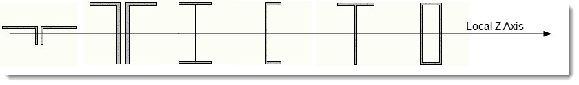
Default Member Orientation
Based on the concept of the member local axis system introduced above, it is now meaningful to describe the default orientation of the various sections that can be assigned to a member in a 2D Frame Analysis model. Of most interest is the default orientation of steel sections. When a steel section is assigned to a member, it will be assumed to be oriented as shown in the following diagram, which references the member local Z axis, the axis that is perpendicular to the plane of the model by default:
 <
<