Member Loads
This tab provides the input locations for all member loads applied to the frame EXCEPT member self weights. Member self weight loads can be automatically generated using the controls on the Load Combinations tab.

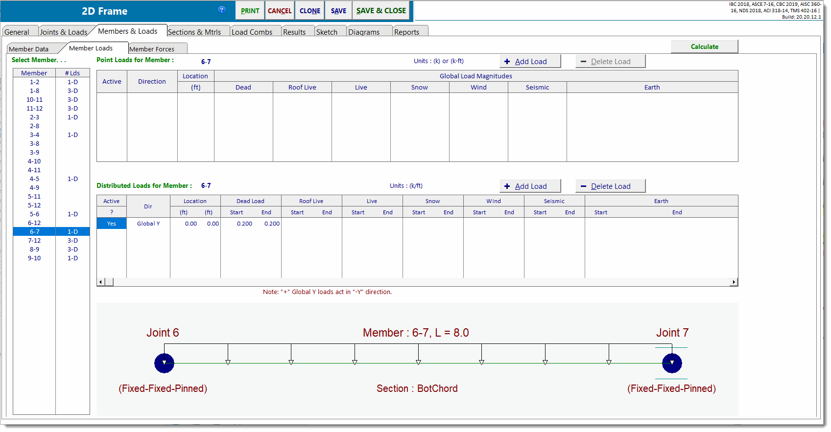
Select Member: lists all members in the model. This is where you click to select a member for which to add/delete/modify loads. This selection controls what is visible on the other two lists and in the graphic image at the bottom. The column labeled # Lds indicates the number and type of loads that have been applied to each member. "P" represents a point load, and "D" is for distributed loads. "1-P, 2-D" means that the member has one point load and two distributed loads applied to it.
Point Loads for Member X: shows the point loads that are applied to the selected member.
Distributed Loads for Member X: shows the distributed loads that are applied to the selected member.
At the bottom is a sketch showing the member and applied loads for reference.
When you click on any item in the two load entry lists, that location in the list will change into a data entry item. The columns in the list have their own specific entry types that will be described below.
Point Loads Entry List

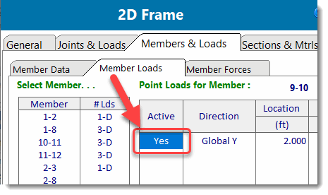
Active
This is a Yes/No checkbox that allows you to turn the load on and off. This is useful when you want to quickly see the effect of removing the load without actually having to delete the load and then potentially have to redefine the load at a later time.

Direction
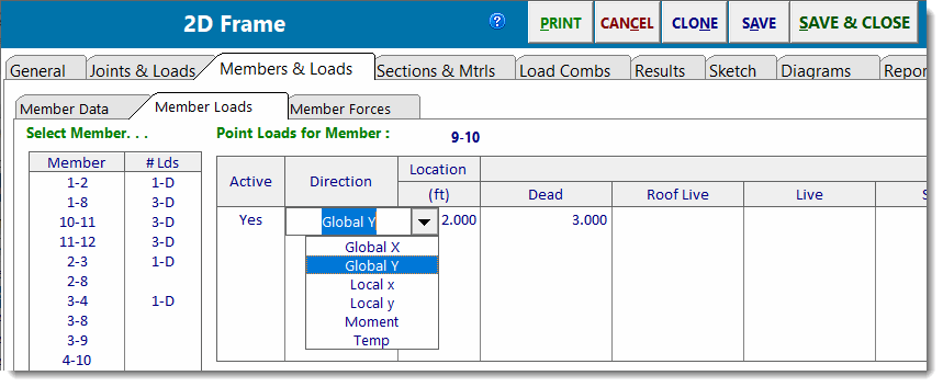
This specifies the direction of application of the load. Here is a description of each direction:
Global X: This point load acts in a direction parallel to the Global X Axis. Entering a positive value will apply the load to the right (in the positive X direction).
Global Y: This point load acts in a direction parallel to the Global Y Axis. The algebraic sign on the magnitude will affect the direction of application based on the Applied Global Y Load Sign Convention setting on the General tab as follows:
When the Applied Global Y Load Sign Convention is set to "Global +Y Loads act towards +Y (Upward)", then loads applied in the Global Y direction with a positive algebraic sign act upward, and loads applied in the Global Y direction with a negative algebraic sign act downward.
When the Applied Global Y Load Sign Convention is set to "Global +Y Loads act towards -Y (Downward)", then loads applied in the Global Y direction with a positive algebraic sign act downward, and loads applied in the Global Y direction with a negative algebraic sign act upward.
In order to most efficiently describe the direction of application of the "Local" load types, it helps to refer to the member local axis system. Each member can be thought of as having its own x, y, and z coordinate axes that are mutually perpendicular and follow the right-hand rule. The orientation of the member local axes can be determined as follows:
1. The local x axis is always parallel to a vector from the "I" node to the "J" node. (This axis is parallel to the longitudinal axis of the member.)
2. The local z axis is always parallel to the Global Z axis.
3. The local y axis can be found by taking the vector cross product of local z cross local x. (Envision using the right hand to rotate the local z axis into the local x axis, and the right thumb will automatically indicate the positive direction of the local y axis.)
Local x: This point load acts parallel to the member's local x axis. If this load is specified with a positive magnitude, the load will act in the positive direction of the local x axis. If this load is specified with a negative magnitude, the load will act in the negative direction of the local x axis.
Local y: This point load acts parallel to the member's local y axis. If this load is specified with a positive magnitude, the load will act in the positive direction of the local y axis. If this load is specified with a negative magnitude, the load will act in the negative direction of the local y axis.
It should now be obvious that it is VERY important to have a thorough understanding of member orientation when using "Local" load types.
Moment: This specifies that the load is a concentrated moment. Positive moments follow the right-hand rule and apply a counter-clockwise rotational force to the member (when viewing the model from the positive Z direction).
Temperature: This is used to specify temperatures at particular locations along the length of a member. The module then uses these spot temperatures, in conjunction with the joint temperatures specified in the Joint Data list, to establish temperature gradients along the member(s). The module will calculate the effects of the specified temperature gradient from the end joint to the location along the member at which the temperature was specified. If you apply more temperature loads, the gradients are developed between each adjacent point of temperature load.

Location
This specifies the distance from the "I" joint where the point load is located.
Load Type & Magnitude
You can enter seven different types of loads on the frame and combine them using the factors on the Load Combinations tab.
Distributed Load Entry List

Active
This is a Yes/No checkbox that allows you to turn the load on and off. This is useful when you want to quickly see the effect of removing the load.
Direction
This specifies the direction of application of the load.

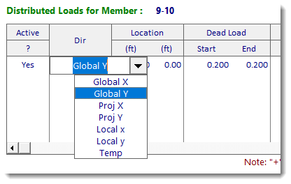
Here is a description of the different directions:
Global X: This load acts in a direction parallel to the Global X Axis and is distributed along the full length of the member. If the member is sloped, the load will be applied for the full length of the member. So if a member has a 10-foot rise and a 10-foot run, the length of the load will equal 14.14 feet. Entering a positive value will apply the load to the right (in the positive X direction).
Global Y: This load acts in a direction parallel to the Global Y Axis and is distributed along the full length of the member. If the member is sloped, the load will be applied for the full length of the member. So if a member has a 10-foot rise and a 10-foot run, the length of the load will equal 14.14 feet. The algebraic sign on the magnitude will affect the direction of application based on the Applied Global Y Load Sign Convention setting on the General tab as follows:
When the Applied Global Y Load Sign Convention is set to "Global +Y Loads act towards +Y (Upward)", then loads applied in the Global Y direction with a positive algebraic sign act upward, and loads applied in the Global Y direction with a negative algebraic sign act downward.
When the Applied Global Y Load Sign Convention is set to "Global +Y Loads act towards -Y (Downward)", then loads applied in the Global Y direction with a positive algebraic sign act downward, and loads applied in the Global Y direction with a negative algebraic sign act upward.
Projected X: This load acts in a direction parallel to the Global X Axis, but it is applied only to the length of the member projected onto the Global Y Axis. So if a member has a 10-foot rise and a 20-foot run, the length of the load will equal 10.00 feet (the rise of the member).
Projected Y: This load acts in a direction parallel to the Global Y Axis, but it is applied only to the length of the member projected onto the Global X axis. So if a member has a 10-foot rise and a 20-foot run, the length of the load will equal 20.00 feet (the run of the member).
In order to most efficiently describe the direction of application of the "Local" load types, it helps to refer to the member local axis system. Each member can be thought of as having its own x, y, and z coordinate axes that are mutually perpendicular and follow the right-hand rule. The orientation of the member local axes can be determined as follows:
1. The local x axis is always parallel to a vector from the "I" node to the "J" node. (This axis is parallel to the longitudinal axis of the member.)
2. The local z axis is always parallel to the Global Z axis.
3. The local y axis can be found by taking the vector cross product of local z cross local x. (Envision using the right hand to rotate the local z axis into the local x axis, and the right thumb will automatically indicate the positive direction of the local y axis.)
Local x: This distributed load acts parallel to the member's local x axis. If this load is specified with a positive magnitude, the load will act in the positive direction of the local x axis. If this load is specified with a negative magnitude, the load will act in the negative direction of the local x axis.
Local y: This distributed load acts parallel to the member's local y axis. If this load is specified with a positive magnitude, the load will act in the positive direction of the local y axis. If this load is specified with a negative magnitude, the load will act in the negative direction of the local y axis.
It should now be obvious that it is VERY important to have a thorough understanding of member orientation when using "Local" load types.
Temperature: This is used to specify temperatures at particular locations along the length of a member. The module then uses these spot temperatures, in conjunction with the joint temperatures specified in the Joint Data list, to establish temperature gradients along the member(s). The module will calculate the effects of the specified temperature gradient from the end joint to the location along the member at which the temperature was specified. If you apply more temperature loads, the gradients are developed between each adjacent point of temperature load.
Location - Start, End
This specifies the distance from the "I" joint to the beginning and end of the load. Leaving BOTH values as zero (0.0) will cause the load to be applied to the full length of the member.
Load Type & Magnitude
You can enter seven different types of loads on the frame and combine them using the values on the Load Combinations tab.