Flitch Plated Wood Beam |
  
|
Flitch Plated Wood Beam |
|
The Flitch Plated Wood Beam module provides an efficient way to evaluate a simply-supported wood beam reinforced with one or more steel flitch plates. It allows both ASD and LRFD, but for simplicity it assumes that the values are already factored appropriately and combined. The module then performs the load distribution to determine the percentage of load attributable to the wood member(s) and to the steel plate(s). Finally, the specified bolts are checked for bearing in accordance with NDS requirements.
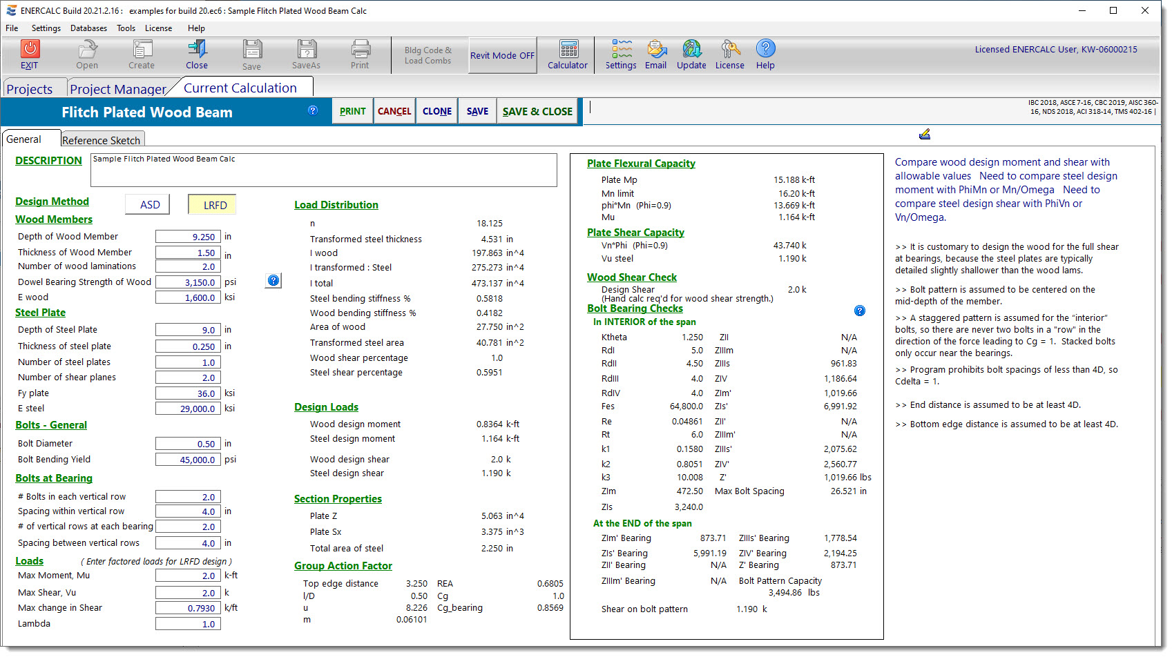
Design Method
Specify ASD or LRFD.
Wood Members
Specify depth and thickness of one individual wood lamination.
Number of laminations input allows multiple of the defined individual wood lamination.
Dowel bearing strength of wood comes from NDS Table 12.3.3, which is provided for convenience with a click of the related help button.
E wood is the modulus of elasticity that will be used. Enter the value of E', as no further adjustment factors are applied to this value.
Steel Plate
Specify the depth and thickness of one individual steel plate.
Number of steel plates input allows multiple of the defined individual steel plate.
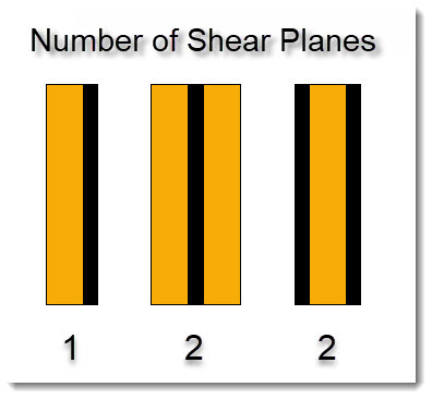
Number of shear planes affects the bolt bearing calculation.
Specify yield strength and modulus of elasticity of the steel plate(s).
Bolts - General
Specify the bolt diameter.
Specify the bolt bending yield strength.
Bolts at Bearing
Specify the number of bolts in each vertical row at the bearing and the spacing within those vertical rows. Then specify the number of vertical rows that occur at each bearing and the spacing between those rows.
Loads
Specify the design loads.
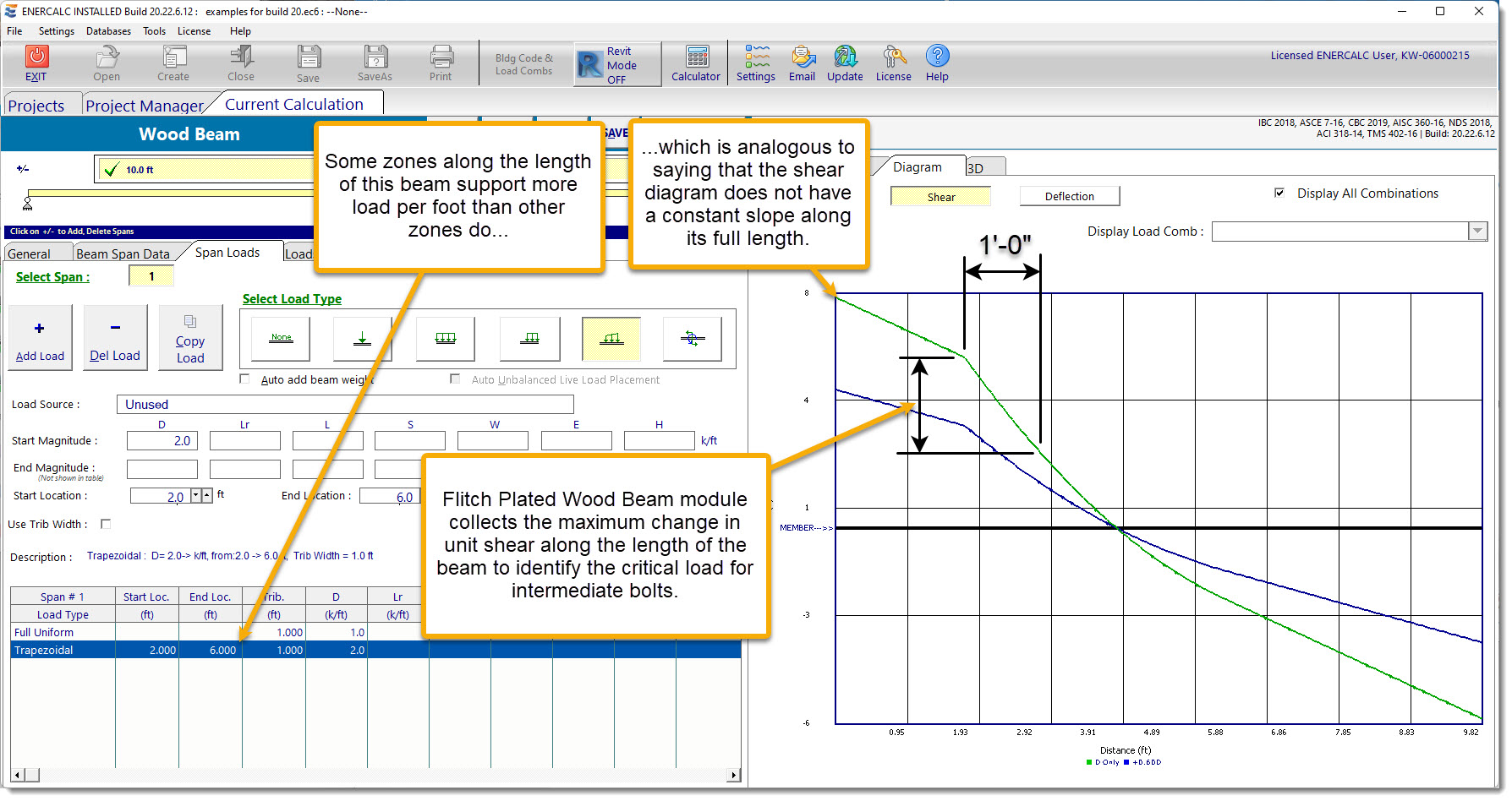
If ASD is used, the input represents the maximum moment, maximum shear, maximum change in shear due to service-level load combinations, and the Load Duration factor, Cd.
If LRFD is used, the input represents the maximum moment, maximum shear, maximum change in shear due to strength-level load combinations, and the Load Duration factor, Lambda.
Note that the following screen capture is NOT from the Flitch Plated Wood Beam module. It is from the Wood Beam module, which supports full loading functions and displays shear diagrams. The screen capture is included to illustrate one method of determining the input value "Maximum Change in Shear" as required by the Flitch Plated Wood Beam module.
Load Distribution
The Load Distribution category presents the calculations to determine the relative flexural stiffness of the wood and the steel based on transformed moments of inertia. It also shows the calculations to determine the relative shear force distribution between the steel and the wood.
Note: The wood members are always conservatively designed to carry the full shear force, because common practice is to detail the steel flitch plates slightly shorter than the wood member to avoid conflicts at the bearing. Therefore the wood must always carry the full shear force at the bearing.
Design Loads
The Design Loads section applies the relative percentages determined in the Load Distribution section to proportion the design moment and design shear between the wood and the steel.
Section Properties
Section properties of the steel plate are presented.
Group Action Factor
The Group Action Factor section reports the values of Cg (for the capacity of bolts in the interior of the span) and Cg_bearing (for the capacity of bolts at the bearings). It also displays the variables used in determining the two group action factors.
Note: A staggered pattern is assumed for the "interior'' bolts, so there are never two bolts in a row in the direction of the force leading to Cg = 1. Stacked bolts only occur near the bearings, so Cg_bearing may have a value less than 1.0.
Plate Flexural Capacity
The Plate Flexural Capacity section presents the calcs to determine the flexural capacity of the plate. The value of Ma or Mu attributable to the plate is reported for easy verification of the flexural capacity.
Note: Flexural buckling is assumed to be prevented by adequate bracing.
Plate Shear Capacity
The Plate Shear Capacity section presents the calcs to determine the shear capacity of the plate. The value of Va or Vu attributable to the plate is reported for easy verification of the shear capacity.
Wood Shear Check
The Wood Shear Check section echoes the design shear force required of the wood member(s). This is convenient for running a quick check on the wood shear capacity by hand, or in the Wood Beam module.
Bolt Bearing Checks in the Interior of the Span
This section determines the capacity of the individual bolts in the staggered pattern in the interior of the span (not at the bearings). It presents the variables used in the checks of the various bolt failure modes, along with the capacities associated with each failure mode. The value of Z' is the lowest of ZIm', ZIs', ZII', ZIIIm', ZIIIs' and ZIV'. Using the Max change in Shear input value, this section reports a theoretical maximum permissible spacing of the bolts in the interior of the span, assuming that the bolts must transfer the "Steel bending stiffness" percentage of the "Max change in Shear" from the wood to the steel plate(s).
Bolt Bearing Checks at the End of the Span
This section determines the capacity of the individual bolts in the pattern at the end of the span (at the bearings). Values are reported for each individual failure mode. The value of Z' Bearing is the lowest of ZIm' Bearing, ZIs' Bearing, ZII' Bearing, ZIIIm' Bearing, ZIIIs' Bearing and ZIV' Bearing. It also presents the capacity of the entire pattern at the bearing, and reports the load on those bolts for easy comparison.
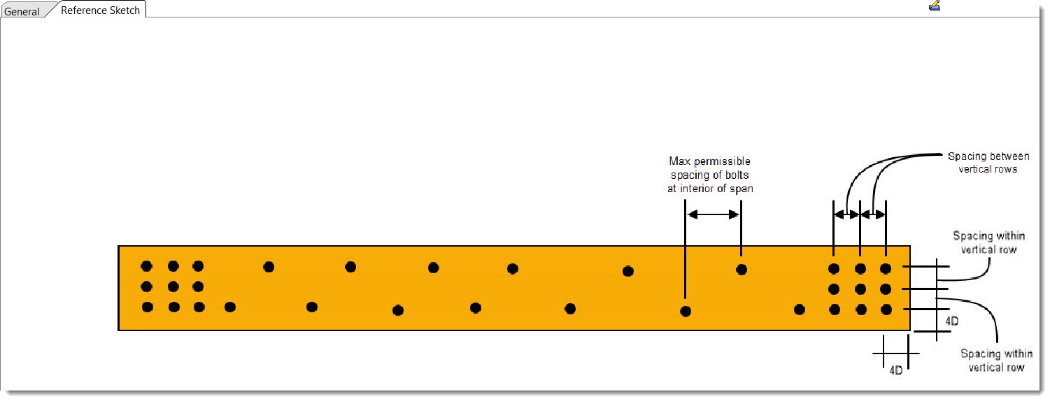
Reference Sketch
The reference sketch is provided to clarify the dimensions collected in the input.
 <
<