Concrete Beam Design |
  
|
Concrete Beam Design |
|
General
The concrete beam module designs concrete rectangular or Tee beams against enveloped bending about strong axis (local z) and enveloped shear along local y. Axial force, bending about weak axis (local y), and torsion are not considered. Furthermore, no deep beam action is considered. If axial force or biaxial bending actions cannot be neglected, the use of column design module is recommended.
Beam Flexural Reinforcement
The beam top and bottom flexural reinforcement is computed at each analysis station along the beam length. Minimum reinforcement is computed for the bottom steel. The program designs each beam against positive or negative moment with single layer of tension steel with tension-controlled condition. For flexural design, the critical section at a support may be taken at the face of the support (but not greater than 0.175 * span length from the support center). The program offers an option to account for these conditions by automatically computing beam support widths from Model Design Criteria under Concrete > Design Criteria.
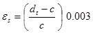
The following algorithm assumes one layer of tension steel, that is, dt = d, the depth of the tension steel centroid. This assumption is made due to its simplicity and conservative nature and is reasonable unless the tension steel strain is very close to 0.005 – the tension-controlled limit strain.
The design result is reflected in top and bottom reinforcement diagrams.
Rectangular Beam Flexural Design Algorithm
Given b, d = dt, d’, fc, fy and Mu find required As (and As’ if needed)
Step 1: Determine maximum moment without compression steel, using the tension-controlled limit![]() and
and ![]() .
.
![]()
![]()
![]()
![]()
![]()
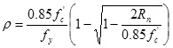
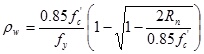
Step 2: If ![]() , design the section as singly-reinforced as follows:
, design the section as singly-reinforced as follows:
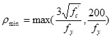
![]()
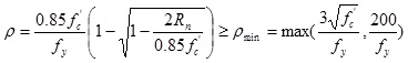 (ACI 318-02/05 10.5.1)
![]()
![]()
![]()
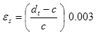
Step 3: If ![]() , design the section as doubly-reinforced as follows (still assuming the tension-controlled limit
, design the section as doubly-reinforced as follows (still assuming the tension-controlled limit ![]() and
and ![]() ):
):
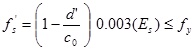
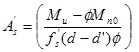
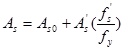
Note, the tensile steel required to balance the compressive steel is
The design fails if fs’ < 0. For practical reasons, the design also fails if ![]() .
.
Tee Beam Flexural Design Algorithm
Given b, bw, hf , d = dt, fc, fy and Mu, find required As
Step a). Assuming a <= hf and tension-controlled section with ![]()
![]()
![]()

If a > hf, go to Step b)
![]()
![]()
If ![]() , the design fails.
, the design fails.
Step b). a > hf and tension-controlled section with ![]()
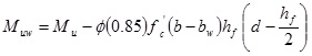
![]()

![]()
If ![]() , the design fails.
, the design fails.
The member shear reinforcement (stirrup spacing) is computed at each analysis station along the member length. Stirrup size and number of legs are assumed uniform along the length of a member as part of input. For shear design, sections located less than a distance d from the face of the support may be permitted to be designed for Vu computed at a distance d from the support (ACI 318-02/05 11.1.3.1). The program offers an option to account for these conditions by automatically computing beam support widths from Model Design Criteria under Concrete > Design Criteria.
The design result is reflected in a stirrup spacing diagram.
Beam Shear Design Algorithm
The shear design for concrete beam is the same as that of concrete column except the axial force is always treated as zero.
 <
<