Concrete Column Design |
  
|
Concrete Column Design |
|
General
The concrete column module designs concrete rectangular or circular columns against axial, uniaxial or biaxial bending as well as shear based on ACI 318-02/05/08/11/14 Code Provisions. The program generates EXACT (not approximate or empirical) P-Mx-My interaction surfaces for all sections according to user-specified design criteria. The capacity ratio is computed for each column based on capacity interaction surfaces and axial force-biaxial bending in each load combination. Slenderness effects are considered for both non-sway (braced) and sway (unbraced) frames. Shear design in columns is based on the shear force envelope with the option to include or exclude axial force influence on concrete shear capacity.
Axial Load and Moment Convention
For concrete design, compressive and tensile axial loads have positive and negative signs respectively. The major moment is designated as Mx in design as opposed to Mz used in analysis output. The minor moment is designated as My in both analysis and design.
Solution Assumptions
•The strain in reinforcement and concrete is directly proportional to the distance from the neutral axis (ACI 318-02/05 10.2.2).
•The maximum usable strain at the extreme concrete compression fiber is equal to 0.003 (ACI 318-02/05 10.2.3).
•The stress of steel is fs = Es * εs but fs <= fy where Es = 29000 ksi, εs is steel strain and fy is the yield strength of steel (ACI 318-02/05 10.2.4).
•The tensile strength of the concrete is neglected in flexural calculation (ACI 318-02/05 10.2.5).
•A uniformly distributed stress of 0.85fc is assumed over an equivalent compression zone bounded by the edge of the cross section and a line parallel to the neutral axis at a distance a = β1* c where c is the distance from extreme compression fiber to neutral axis (ACI 318-02/05 10.2.7.1).
•β1 = 0.85 – 0.05 * (f’c - 4) and 0.65 <= β1 <= 0.85 and f’c unit is ksi
•Reinforcement ratio ρ should be 1% <= ρ <= 8% for column sections (ACI 318-02/05 10.2.7.3).
Solution Algorithms
1. All sections are EXACTLY solved biaxially based on the solution assumptions above. Each section is solved based on the following steps.
2. Nominal Strength Calculation (Pn, Mnx, Mny)
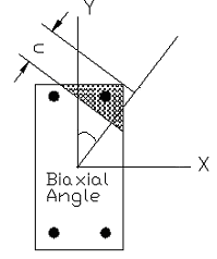
2a. The nominal capacity of a section is computed at successive choices of biaxial angles. The choices of angles are based on the user input for biaxial angle steps found in the command Concrete > Design Options. Biaxial angle steps affect the solution accuracy and speed. For biaxial problems, steps must be multiples of 4. A value of 16 ~ 32 is sufficiently accurate for most sections. The adequacy of biaxial angle steps can be determined by smoothness of the Mx-My interaction diagram. For uniaxial problems, biaxial angle steps should be set to 4. This will give P-Mx (+) at 0 degree angle, P-Mx (-) at 180 degrees angle, P-My (+) at 90 degree angle, P-My (-) at 270 degrees angle.
The number of biaxial angle steps is analogous to the number of sides of a polygon used to approximate a circle or ellipse. A uniaxial solution in the program is therefore analogous to using a square to approximate a circle or a rectangle to approximate an ellipse. A biaxial solution with 16 angle steps is analogous to using a 16-sided polygon to approximate a circle or an ellipse. Obviously, the 16-sided polygon is closer or more accurate to approximate a circle than a square. The moral of this comparison is that a low value of biaxial angle steps tends to give more conservative biaxial capacity for the section.
2b). For each biaxial angle, Pn, Mnx, Mny and maximum tensile steel strain εt are computed at successive choices of neutral axis distance c using strain compatibility and stress-strain relations to establish bar forces and the concrete compressive results. The choices of c are based on the neutral axial steps found in the command Concrete > Design Options. Neutral axial steps affect the solution accuracy and speed. A value of 250 ~ 500 for neutral axis steps is sufficiently accurate for most sections. The adequacy of neutral axis steps can be determined by smoothness of the P-Mx and/or P-My interaction diagrams. In addition, the program always computes several control points. They are maximum Pn (compression), minimum Pn (tension), fs = 0; 0.25fy; 0.5fy and 1.0fy (balanced condition). Concrete displaced by steel may be optionally included or excluded (by default).
2c). Mnx-Mny contour curves are computed for successive choices of axial forces. This is achieved through interpolation on the Pn, Mnx and Mny already calculated for each biaxial angle in the procedure above. The choices of axial forces are based on the neutral axial steps found in the command Concrete > Design Options.
3. Design Strength Calculation (φPn, φMnx, φMny)
Design strength according to ACI 318-02,05/08/11/14 is obtained by multiplying Pn, Mnx and Mny of each biaxial angle by applying strength reduction factor φ as determined in the following (ACI 318-02/05 9.3.2):
Φc = 0.65, α = 0.80 for tied confinement
Φc = 0.70, α = 0.85 for spiral confinement for ACI 318-02/05
Φc = 0.75, α = 0.85 for spiral confinement for ACI 318-08/11/14
For (εt <= εy, compression-controlled sections)
φ = Φc
For (εt > 0.005, tension-controlled sections)
φ = 0.90
For (εy < εt < 0.005)
φ = Φc + (0.9 - Φc) * (εt - εy ) / (0.005 – εy)
where εt is maximum tensile steel strain for the biaxial angle and εy is steel yield strain (at balanced condition)
In addition, φ Pn must be always less than the following (ACI 318-02/05 10.3.6.1)
Φc * α * [ 0.85 * fc’ * (Ag – As) + fy * As] if concrete displaced by steel is excluded or
Φc * α * [ 0.85 * fc’ * Ag + fy * As] if concrete displaced by steel is not excluded.
4. Capacity Ratio
Capacity ratio is computed for each section based on the loads and the capacity of the section. It is defined as the following:
For a given load set (Pu, Mux, Muy), find the section capacity Mx-My contour at φPn= Pu. The capacity ratio for the load set is the larger of:
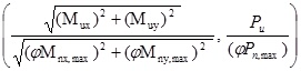
Where (φMnx,max, φMny, max) is the interaction point between the line from point (Mux, Muy) to point (0, 0) and the Mx-My contour line. is the maximum compression or tension capacity of the section, depending on the positive or negative sign of Pu. If Pu is outside the maximum compression or tension capacity, a capacity ratio of 99.9 is assigned.
A capacity ratio equal or less than 1.0 means the design strength is greater than the required strength; and the section is adequate to resist all input loads. A capacity ratio greater than 1.0 means the design strength is less than the required strength and the section is inadequate to resist all input loads. It is important to realize that capacity ratio defined in the program is just a measure of section adequacy against loads. It should not be equated to a factor of safety.
Capacity Ratio Calculation Example
To illustrate the calculation of capacity ratio in the program, see the following example.
For a given load set (Pu, Mux, Muy) = (333 kip, 180 ft-kip, 125 ft-kip), a Mx-My capacity contour at φPn = 333 kip is obtained as shown below. In addition, the maximum compression capacity = 1050.2 kip.
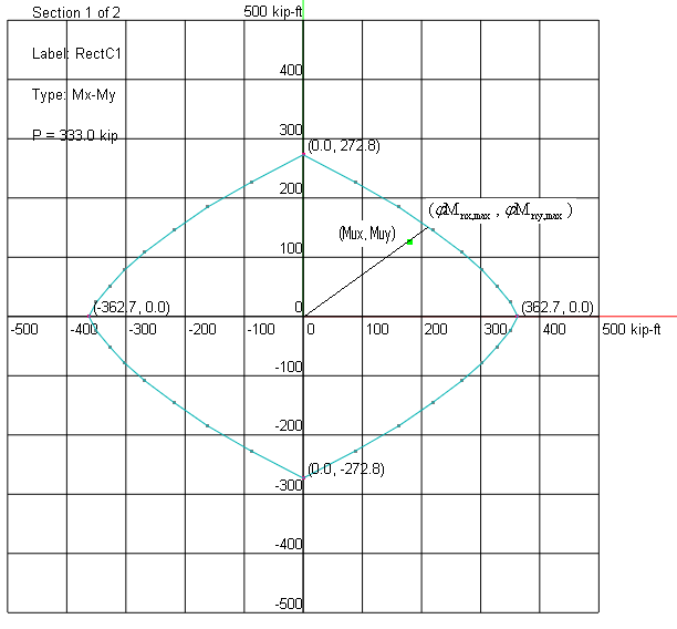
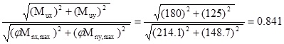
The interaction point between the line from point (180 ft-kip, 125 ft-kip) to point (0, 0) and the contour line is obtained as (214.1 ft-kip, 148.7 ft-kip)
![]()
Therefore, the capacity ratio corresponds to the load set is 0.841. The section is adequate to resist the load.
Two types of second-order moment effects may develop in a frame.
1). P-δ effect is associated with individual member curvature. Additional second-order moment may develop by member (usually a column) axial force (P) acting upon the lateral deflection (δ) of the column axis away from the chord connecting the column ends. It is possible to account for P-δ effects on columns independently.
2). P-Δ effect is associated with the lateral drifts of the frame members. Additional second-order moment may develop by axial force (P) acting upon the lateral translation (Δ) of the frame nodes relative to their original position. It is NOT possible to account for P-Δ effects on columns independently.
For a non-sway frame, P-Δ effect may be safely ignored and the first-order structural analysis is therefore sufficient. The program then accounts for P-δ effect by magnifying the first-order moments using ACI moment magnification method.
For a sway frame, the second-order structural analysis must be performed to account for P-Δ effect. In addition, the program accounts for P-δ effect by magnifying the second-order moments using ACI moment magnification method. In fact, all columns in sway frames must first be considered as braced columns under gravity loads acting alone.
The column is considered braced if one of the following two criteria is met:
Criterion 1: Increase in column end moment due to second-order effects is less than 5% of the first-order moment
Criterion 2: Stability index Q for the column story under consideration from the first-order analysis
![]() (ACI 318-02/05 Eq10-6)
(ACI 318-02/05 Eq10-6)
Section Properties for Structural Analysis and Computing K
It is important to point out that in both first- and second-order analyses; appropriate member stiffness must be used to account for the effects of axial loads, cracking, and creep.
![]() for normal weight concrete
for normal weight concrete
![]() for wc between 90 and 155 lb/ft3
for wc between 90 and 155 lb/ft3
Moment of inertia (ACI 318-02/05 10.11.1)
= 0.35 Ig for beams and cracked walls
= 0.70 Ig for columns and uncracked walls
= 0.25 Ig for flat plates and flat slabs
Area
A = 1.0 Ag
Note:
a). Ig and Ag are based on the gross concrete cross section, neglecting reinforcement.
a). Ig for Tee beams can be closely approximated as 2 times Ig for the web.
b). 0.70 Ig should be used for walls first. If the factored moments and shears indicate that a portion of the wall will crack due to stresses reaching the concrete modulus of rupture, the analysis should be repeated with 0.35 Ig for the cracked portions of the wall.
[Ref. 16 pp577]
The program allows a user to modify the moments of inertia through Element Cracking Factor from Concrete > Cracking Factors. In order to use stiffness reduction, you also need to check “Use cracked section properties (Icr) for members and finite elements” in Analysis Options. This allows you to consider or ignore cracking in the analysis without re-entering element cracking information.
Radius of Gyration
![]()
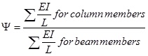
Find relative stiffness ratios (![]() ) of columns and beams at the top and bottom joints of the column
) of columns and beams at the top and bottom joints of the column
Section properties are the same as used in the first-order analysis (step 1)
For practical reasons, ![]() for fixed end and
for fixed end and ![]() for hinged end.
for hinged end.
The effective length factor K is solved from the from the following equations
For braced frames:
![]()
For unbraced frames:
![]()
The program provides a tool to calculate the effective length factor K based on the input![]() . The equations above provide a more accurate K calculation than what is given by (ACI 318-02/05 10.12.1)
. The equations above provide a more accurate K calculation than what is given by (ACI 318-02/05 10.12.1)
The unsupported lengths Luy, Luz of a column are the clear distances between lateral supports in column local y and z directions (ACI 318-02/05 10.11.3.1). A zero value of Lu means that it is equal to the member length between the end nodes.
For non-sway frames, an optional check is made kLu / r <= 34 – 12(M1/M2) (ACI 318-02/05 Eq10-7). Braced frame k is used here. Lu is unbraced length in local x and y directions. M1 and M2 are the smaller and larger factored end moments on the compression member respectively. (M1/M2) is positive if the member is bent in single curvature and negative otherwise.
For sway frames, an optional check is made kLu / r <= 22 (ACI 318-02/05 10.13.2). Sway frame k is used here.
Minimum Moments
The program calculates minimum moments for both braced and unbraced frames,
![]() , where h is in inches (ACI 318-02/05 10.12.3.2). The program conservatively applies the minimum eccentricity about both axes simultaneously.
, where h is in inches (ACI 318-02/05 10.12.3.2). The program conservatively applies the minimum eccentricity about both axes simultaneously.
Equivalent Moment Factor Cm (ACI 318-02/05 10.12.3.1)
![]() if M1 = 0 or M2 = 0
if M1 = 0 or M2 = 0
![]() if transverse load exists
if transverse load exists
![]() if end moments only. (ACI 318-02/05 Eq10-13).
if end moments only. (ACI 318-02/05 Eq10-13).
Although not required, the program also conservatively applies ![]() for ACI 318-08 /11/14.
for ACI 318-08 /11/14.
The sign of ![]() is: positive if the column is bent in single curvature, negative otherwise.
is: positive if the column is bent in single curvature, negative otherwise.
Note, Cm is only applicable to non-sway frames. You have the conservative option to always use Cm = 1.0 from Model Design Criteria under Concrete > Design Criteria.
Section Properties for Critical Loads Computation
The EI used in the frame analysis above is an average value. In designing individual columns, the following reduced EI should be used to reflect the greater chance of cracking:
 (ACI 318-02/05 Eq10-12)
The ratio of maximum factored axial sustained load to maximum factored axial total load. The factor ![]() accounts for the effects of creep.
accounts for the effects of creep.
Generally: ![]()
Critical Load Pc
![]() where
where ![]() (ACI 318-02/05 Eq10-10)
(ACI 318-02/05 Eq10-10)
Moment Magnification Factor
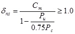 (ACI 318-02/05 Eq10-9)
Pu is the average of axial force at both ends. If ![]() , the design fails and a capacity ratio of 999.9 is assigned.
, the design fails and a capacity ratio of 999.9 is assigned.
Other Requirements
Reinforcement ratio for columns:
Bar requirements: minimum 4 bars for tied columns, 6 bars for spiral columns.
Tie requirements: >= #3 for No. 10 longitudinal bars and smaller; >= #4 for No. 11 14, 18 longitudinal bars.
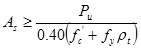
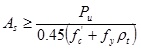
Column Trial Size
The ACI code requires that the reinforcement ratio for columns be within ![]() . It is usually economical to have
. It is usually economical to have ![]() .
.
For tied columns
For spiral columns
Based on rectangular or circular sections used for analysis, the program will generate column sections with different reinforcement configurations.
Column Shear Reinforcement
The column shear design is based on
![]() (ACI 318-02/05 Eq11-1)
(ACI 318-02/05 Eq11-1)
where![]() .
.
Given bw, d, fc, fy, number of stirrup legs n, and stirrup (tie) area Av, the required stirrup spacing is computed at every analysis station.
Concrete shear strength
1. For Pu < 0 (column subjected to tension)
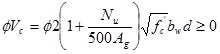 (ACI 318-02/05 Eq11-8)
2. For Pu >= 0 (column subjected to compression)
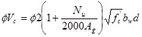 (ACI 318-02/05 Eq11-4)
Note:
•For circular section, ![]() and d = 0.8(2R) where R is the radius of the circular section. (ACI 318 11.3.3 and 11.5.7.3)
and d = 0.8(2R) where R is the radius of the circular section. (ACI 318 11.3.3 and 11.5.7.3)
•Nu = 0 if the influence of compression on concrete shear strength is ignored.
•![]() (ACI 318 11.1.2)
(ACI 318 11.1.2)
•![]() ksi in design of shear reinforcement. (ACI 318-02/05 11.5.2)
ksi in design of shear reinforcement. (ACI 318-02/05 11.5.2)
•Light-weight concrete is not considered.
•Torsional forces are not considered.
The following is the algorithm used to compute the stirrup (tie) spacing(s) in the program.
If![]() , the design fails (ACI 318-02/05 11.5.7.9).
, the design fails (ACI 318-02/05 11.5.7.9).
If ![]() , no stirrup required (ACI 318-02/05 11.5.6.1). The program does not check member depths when applying minimum shear reinforcement for ACI 318-08/11/14.
, no stirrup required (ACI 318-02/05 11.5.6.1). The program does not check member depths when applying minimum shear reinforcement for ACI 318-08/11/14.
If![]() , smax <= min(d/2, 24 in) (ACI 318-02/05 11.5.5.1)
, smax <= min(d/2, 24 in) (ACI 318-02/05 11.5.5.1)
If![]() , smax <= min(d/4, 12 in) (ACI 318-02/05 11.5.5.3)
, smax <= min(d/4, 12 in) (ACI 318-02/05 11.5.5.3)
If ![]() , s = min
, s = min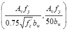 <= smax (ACI 318-02/05 11.5.6.3)
Otherwise, s = ![]() <= smax (ACI 318-02/05 Eq11-15)
<= smax (ACI 318-02/05 Eq11-15)
According to ACI 318-02/05, column confinement spacing shall not exceed 16 longitudinal bar diameters, 48 tie bar or wire diameters, or the least dimension of the compression members.
The following additional requirements are needed for column spirals:
•The maximum center-to-center spacing:
s < 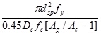 (Derived from ACI 318-02/05 Eq10-5)
•The clear spacing between successive turns shall not exceed 3 inches, nor be less than 1 inch. (ACI 318-02/05 7.10.4.3)
 <
<