Geometric Stiffness Matrix |
  
|
Geometric Stiffness Matrix |
|
When a tensile axial force is present in a member, the bending stiffness of that member is increased. Conversely, when a compressive axial force is present in a member, the bending stiffness of that member is reduced. The stiffness matrix that reflects this kind of stress stiffening effect is called the geometric stiffness matrix [Ref. 3, 7]. It is determined by the element geometry and stress conditions, and is independent of the elastic properties. The geometric stiffness matrix is very effective in accounting for the P-Delta effect and is implemented in the program. It may also be used to perform buckling analysis of the structure but is not implemented in the program directly.
Like the elastic stiffness matrix, the geometric stiffness matrix is of size 12 x 12 and is given [Ref. 3, 7] as follows:
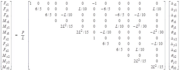
where P is the average of the axial forces (positive in tension, negative in compression) at the member ends.
When the linear static (first order) analysis is chosen, the member stiffness matrix is the elastic stiffness matrix. When the P-Delta (second order) analysis option is chosen, the member stiffness matrix is the summation of the elastic stiffness matrix and the geometric stiffness matrix. You may set the appropriate analysis option with the command Analysis > Analysis Options.
 <
<