Four-Node Shell Local Coordinate System |
  
|
Four-Node Shell Local Coordinate System |
|
The local coordinate system of a shell is determined by its four nodes, and an element local angle. The default (local angle equals 0 degrees) local coordinate system of a four-node shell is defined based on the shape of the shell element.
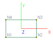
Rectangular Shell |
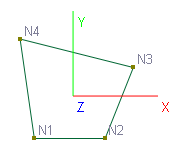
Non-Rectangular Shell |
|---|---|
|
|
For rectangular shells, the default local coordinate system is easily defined by the following: local x points from N1 to N2, local y points from N1 to N4 and local z is perpendicular to the shell surface.
For non-rectangular shells, the default local coordinate system is defined using the following procedures:
Steps |
Description |
Mathematical Notations |
|---|---|---|
A |
Local z is perpendicular to the shell surface |
Let V1 = N2 – N1, Let V2 = N4 – N1 Vz = V1 x V2 |
B1 |
For horizontal shells that are parallel to global XZ plane, local x is parallel to global X
|
For horizontal shells Vx = VX |
B2 |
For non-horizontal shells, Vx is perpendicular to a plane formed by VY and Vz |
For non-horizontal shells Vx = VY x Vz |
C |
Vy is determined based on Vx and Vz and the right-hand rule |
Vy = Vz x Vx |
For a shell with a non-zero local angle (γ), first follow the procedures above that determine the default local coordinate system. Then rotate the default system a γ angle about is its local z vector Vz. The rotated Vx, Vy and Vz define the local coordinate system. The figure below shows the local coordinate systems of some shell elements with different local angles (γ)
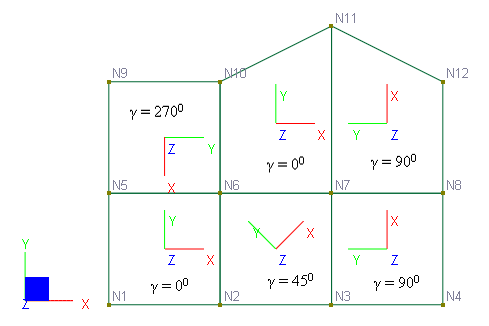
Local coordinate systems for shells with different local angles
 <
<