RC Model Design Criteria |
  
|
RC Model Design Criteria |
|
Concrete Design > RC Design Criteria prompts you with the following dialog.
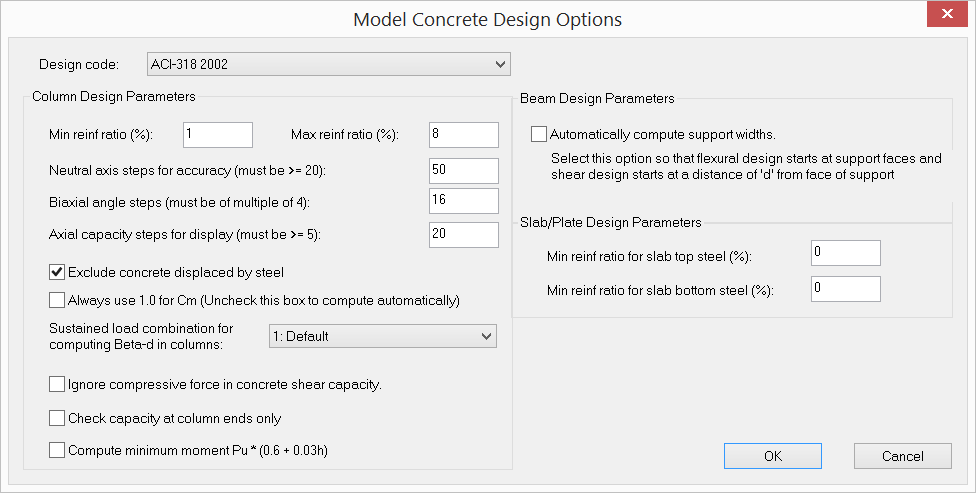
It allows you to enter global options for concrete design. You are encouraged to read the method of solution in the technical part of this document in order to understand these options. You should use this command before performing concrete design.
Design Code |
Specifies design codes. Currently the program supports ACI 318-02/05/08/11/14 only. |
|---|---|
Column min and max reinforcement ratios |
Column minimum and maximum reinforcement ratios are used to generate column sections. They should be set between 1% and 8%. For all practical purposes, the maximum reinforcement ratio should be less than 4% to avoid rebar congestion. |
Neutral axis steps for accuracy |
Neutral axis steps affect the solution accuracy and speed. A value of 250 ~ 500 for neutral axis steps is sufficiently accurate for most sections. The adequacy of neutral axis steps can be determined by smoothness of the P-Mx and/or P-My interaction diagrams. |
Biaxial angle steps |
Biaxial angle steps affects the solution accuracy and speed. For biaxial problems, steps must be multiple of 4. A value of 16 or 32 is sufficiently accurate for most sections. The adequacy of biaxial angle steps can be determined by smoothness of the Mx-My interaction diagram. For uniaxial problems, biaxial angle steps should always be set to 4. This will give P-Mx (+) at 0 degree angle, P-Mx (-) at 180 degrees angle, P-My (+) at 90 degree angle, P-My (-) at 270 degrees angle. |
Axial capacity steps for display |
Specifies the number of axial steps for the display of interaction diagrams / surfaces and result data in the spreadsheet. This value should be smaller than neutral axis steps. A value of 20 to 50 is usually adequate. |
Exclude concrete displaced by steel |
Should almost always be checked. This option is provided for verifications with textbooks only! |
Always use 1.0 for Cm |
If this option is checked, Cm = 1.0 will be used for all concrete columns. Otherwise, the program will compute Cm automatically based on moment curvature and the existence of transverse loading on the column. |
Sustained load combination for computing Beta-d in columns |
Specify the load combination that contains the all sustained load cases with each case load factor equal to 1.0. |
Ignore compressive force in concrete shear capacity |
Specify whether or not to ignore the increase in column concrete shear capacity due to the influence of compressive force. Axial forces are ignored on concrete beams. |
Check capacity at column ends only |
If this option is checked, column capacity is checked at its ends only. Otherwise, column capacity is checked at every station along the column that analysis outputs. |
Compute minimum moment |
If this option is checked, a minimum moment Pu * (0.6 + 0.03h) is used for design |
Automatically compute support widths |
Select this option so that flexural design starts at the support faces and shear design starts at a distance of ‘d’ from the face of support. |
Slab/plate min. reinf. ratios |
Specify slab/plate minimum top and bottom reinforcement ratios for design. According to ACI 318-02/05/08/11 7.12.2.1, area of shrinkage and temperature reinforcement shall provide at least 0.18% of gross concrete area. |
 <
<