Drawing Grid Setup |
  
|
Drawing Grid Setup |
|
Create > Grids & Snaps > Drawing Grid Setup offers the controls to configure the grid used for snapping and dimensional control. The command prompts you with the following dialog.
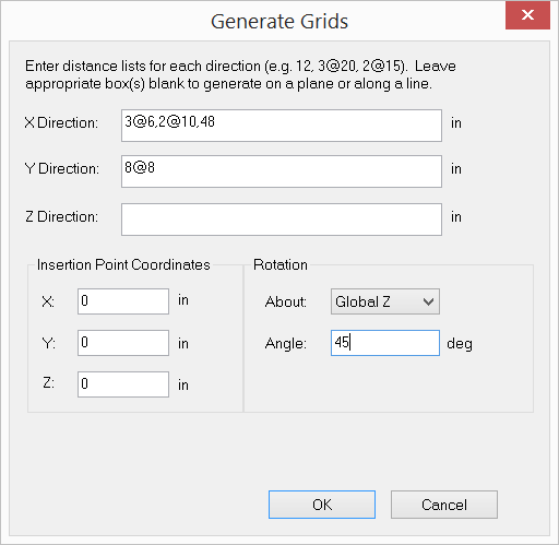
It allows you to generate a 1D, 2D or 3D rectangular grid for drawing or guidance. The distance list is a comma separated list that specifies multiple distances. For example, a distance list of “12, 2@14, 3@10” will generate distances of 12, 14, 14, 10, 10 and 10 in length units. You may specify a distance list for the X, Y, or Z direction or any combination of them.
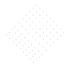
You may specify an insertion point to translate and rotation parameters to rotate the grid. The drawing grid may be turned on or off by running the command View > Grids & Snaps > Drawing Grid or by simply pressing F7. You may regard the grid as a user defined coordinate system that can be changed at any time. The coordinates of the grid intersection under the mouse are displayed in the status bar. It helps you to identify correct points when drawing nodes or elements.
The following example shows the use of this command.
 <
<