Sections |
  
|
Sections |
|
Create (or Modify) > Member Properties > Member Sections prompts you with the following dialog.
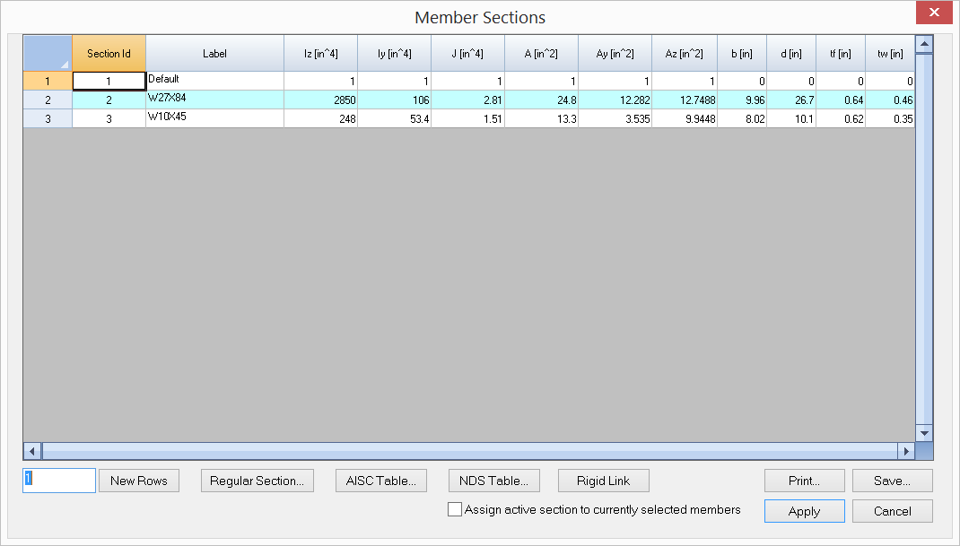
It allows you to define and/or assign sections to selected members in the model. An ID is assigned automatically to each section by the program and may not be changed. You may assign a label with 127 maximum characters to each section for easy identification. The section properties include:
•moment of inertia about major axis (Iz)
•moment of inertia about minor axis (Iy)
•torsional moment of inertia (J)
•section area (A)
•shear area in the local y direction (Ay)
•shear area in the local z direction (Az).
These properties are used in the analysis. Other properties (B, H, Tf and Tw) are dimensions for regular sections such as rectangular, circular, wide flange sections. These dimensional properties are used for graphic rendering only (not used in analysis).
You may add one or more sections by clicking the “New Rows” button. You may also print all sections in the list by clicking the “Print” button. The “Assign active section to currently selected members” checkbox may be used to assign the active section to selected members. The active section refers to the one that currently has focus in the list in the dialog. In order for section assignments to take place, members must be selected beforehand.
A more flexible way to assign member properties is to use Modify > Member Properties command, which allows you to continuously assign one or more properties to members.
Note: The section property input does not include Ixy – the product of inertia. For a section where Ixy is not zero such as an angle, the principal axes of a cross section are different from its geometric axes. In such situations, you should enter section properties in its principal axes and adjust the member element local angle accordingly.
You may add a regular section by clicking the “Regular Section” button. The program displays the following dialog.
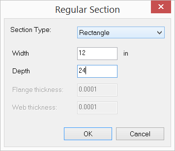
Three regular sections are currently provided by the program, namely rectangular, circular, wide flange and Tee sections. The properties of these sections are calculated automatically.
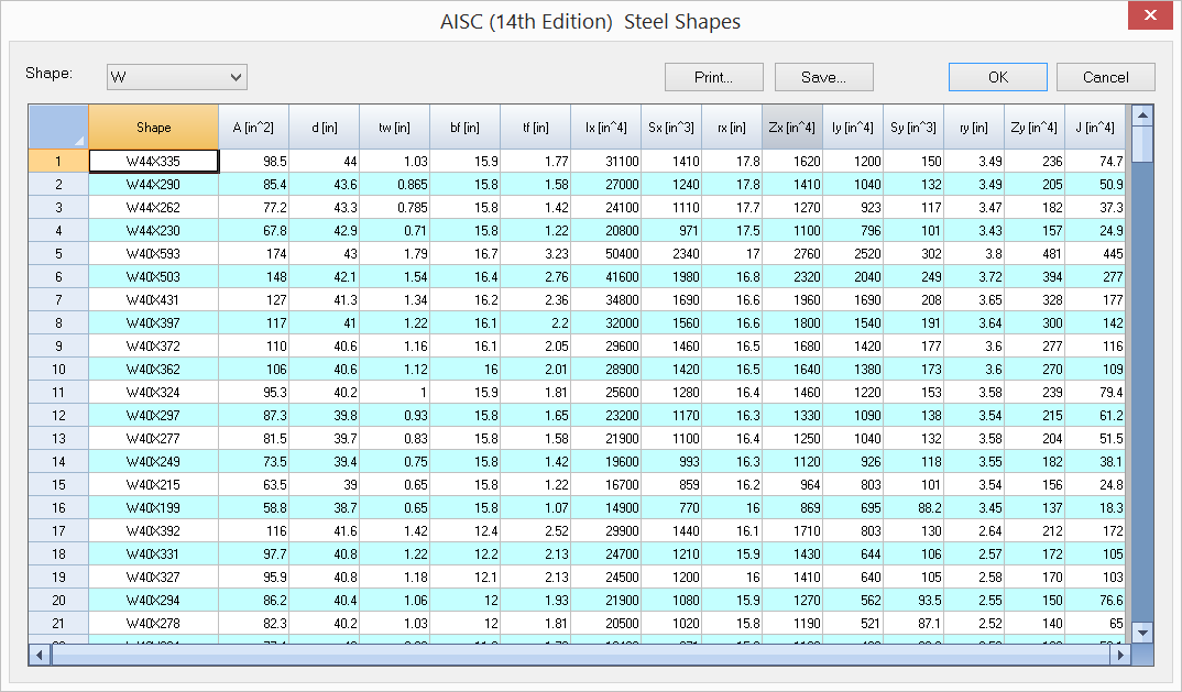
You may also add sections from the AISC steel shape table (above) or NDS wood shape table. You should not modify an AISC or NDS shape label or its properties.
You may create one and only one rigid link section for use in the model by simply click “Rigid Link” button. A rigid link is a member that has very large sectional properties (A, Ay, Az, Iz, Iy and J). There can only be one rigid link section defined in the model and it must be named as “RIGID_LINK”. The properties for the RIGID_LINK section must be set to 0’s on the member section dialog. The program will appropriately calculate A, Ay, Az, Iz, Iy and J during the solution process. Self weight for rigid links will be ignored by the program.
The program always has a default section labeled “Default”. You may not delete this section or change its label. You may, however, change its properties.
 <
<