Deflection Diagram |
  
|
Deflection Diagram |
|
Analysis Results > Deflection Diagram prompts you with the following dialog.
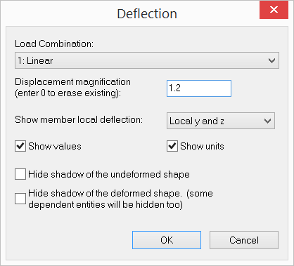
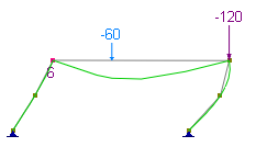
It allows you to view the deflected shape of the model for the selected load combination. The deflected shape is constructed by adding nodal displacements to nodal coordinates. For members, you have the option to show the local y and/or z deflection as well. You need to adjust the displacement magnification to view the deflection properly. The deflection displayed is for the selected load combination only. However, you may display deflections for different load combinations in multiple windows. To open a new window, click Window > New Window. The deflection values and units may be shown for the member local deflections. You may choose to have shadows of the undeformed shape and deformed shape hidden.
You cannot perform mouse selection while the deflected shape is shown. However, you may open another window with the undeformed shape and perform mouse selection as usual.
 <
<