In this section, for each input tab we will review only the items that are unique to the STEEL material type.
For general information on the typical data input for all beams see the Beams topic.
This module offers complete design of single and multi-span steel members. Among its capabilities are:
•Single or multi-span beams.
•End fixity can be pinned, fixed, free or a combination.
•Steel member analysis and design are according to AISC 360.
•ASD or LRFD design methods can be selected.
•A complete steel section database is provided.
•Unbraced compression edge lengths can be specified in a variety of ways.
•Automatic member selection is provided.
General
When steel is used, this tab includes input fields to set the values for yield stress and elastic modulus, as well as an option to set the Cb factor equal to 1, as shown in the screen capture below:
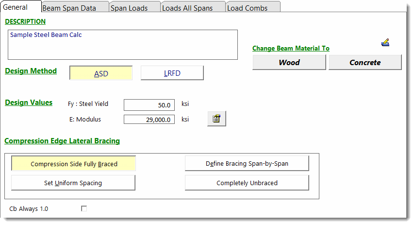
If Cb is not forced to 1, the program automatically calculates Cb based on the moment and direction of curvature at various locations along the beam.
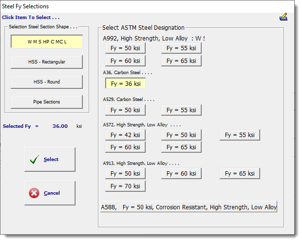
For convenience the module includes a built-in steel database. Click the ![]() button to the right of the Fy entry and you will see the following table, which offers a number of commonly used steel grades:
button to the right of the Fy entry and you will see the following table, which offers a number of commonly used steel grades:
Beam Span Data
When steel is selected, the beam size selection is specifically for steel. You can select a section in 4 ways:
1 - Simply type the AISC name into the Steel Section Name field and press [Tab].
2 - Click the  button and select from the built-in AISC section database.
3 - Click the [Auto Select] button to have the module evaluate steel sections from the database according to your criteria.
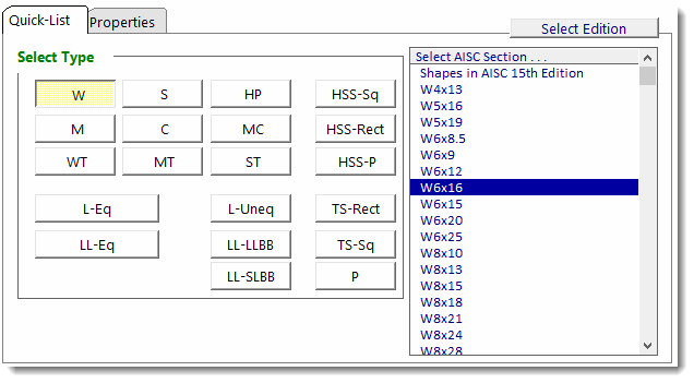
4 - Select a steel section from the Quick-List tab as shown below:
Span Loads
No differences from other materials.
Loads All Spans
No differences from other materials.
Load Combinations
No differences from other materials.
Results Tab
This set of tabs provides detailed results for the current calculation. The tabs in the upper right-hand corner of the screen allow you to select the major areas available for review: Calculations, 2D Sketch, Diagram and 3D Rendering.
The Calculations tab offers the following results options:
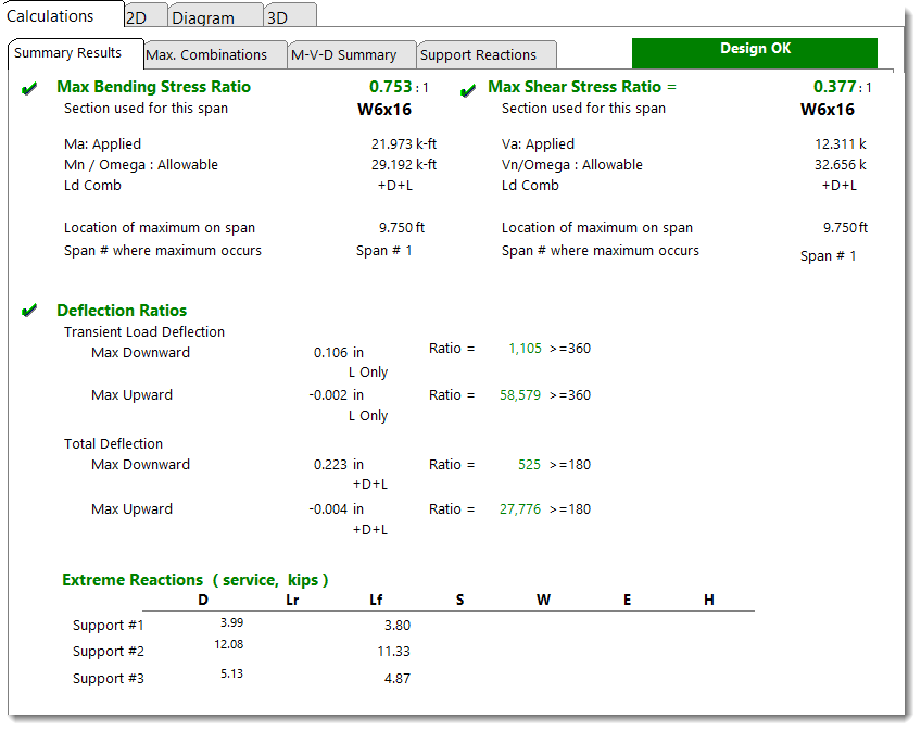
Summary Results provides details for shear, moment and deflection for the governing load combinations.
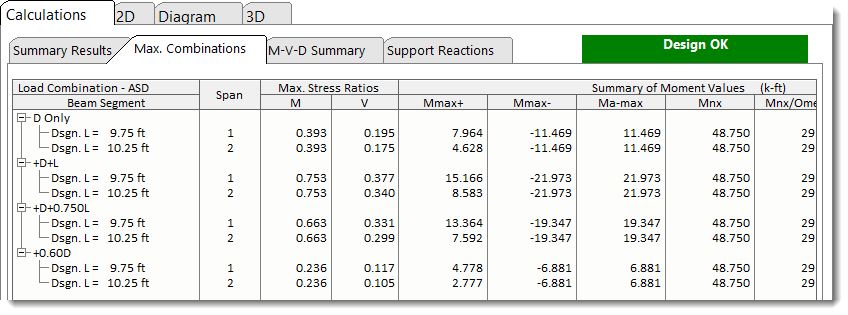
Max. Combinations provides detailed results for each beam segment for each load combination. The leftmost column lists the load combinations and the unbraced length being considered.
These results are a consolidation of the highly detailed incremental results on the M-V-D Summary tab.
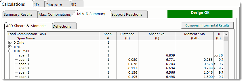
M-V-D Summary - Shears & Moments shows highly detailed moment and shear information for each beam and for each load combination. For multi-span beams using Automatic Unbalanced Live Load Placement there may be thousands of lines of results.
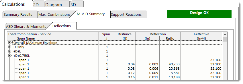
M-V-D Summary - Deflections shows highly detailed deflection results for all load combinations.
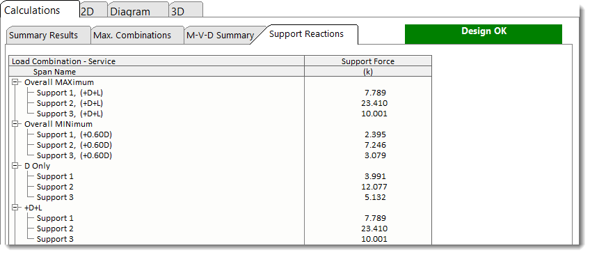
Support Reactions shows reactions for each support for each load condition.
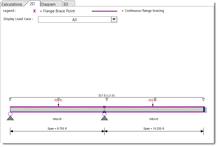
The 2D Sketch tab provides a graphic representation of the beam currently being designed:
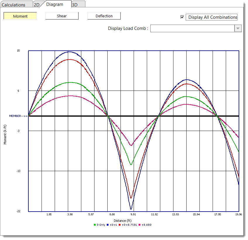
The Diagram tab offers the ability to view shear, moment, and deflection diagrams for selected load combinations:
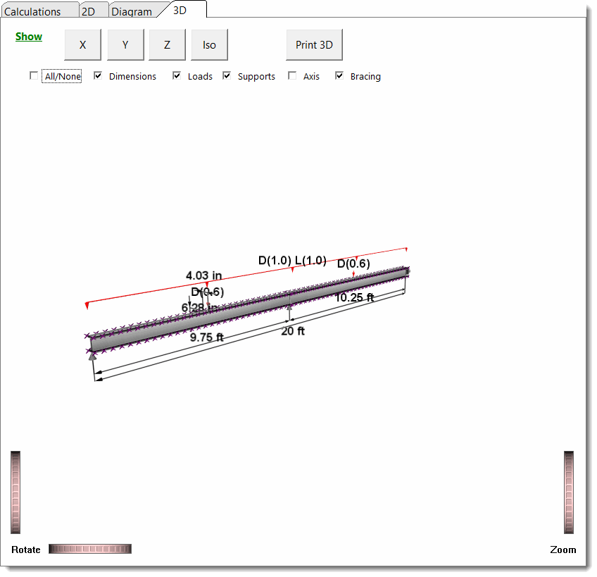
The 3D Rendering offers a 3D view of the beam with many display controls:
