Steel Base Plate FEM |
  
|
Steel Base Plate FEM |
|
This module applies engineering principles to the design of a steel base plate though the use of a finite element analysis of the plate.
General
AISC provides solutions for steel base plates with various loads in Design Guide 1. But the design guide does make some simplifying assumptions (infinitely rigid substrate, uniform or triangular bearing pressure of a certain magnitude, extent of bearing pressure, etc). And the design guide also has some limitations (concentric loading). While the design guide has proven to be a reliable design reference over the years, there are some applications where a different tool is required. The purpose of this module is to provide an alternative to the design guide.
The methods of this module are based in engineering principles, but it should be noted that it employs Finite Element Analysis and a different set of assumptions (spring support, non-uniform bearing pressure) to arrive at code-compliant designs. For this reason, one should not be surprised to see that the module results in a different design than the AISC Design Guide methods, even when the same starting parameters are entered, such as for one of the design guide examples.
Flexural Design Approach
The code dictates that Mn shall be calculated with the smaller of Z or 1.6S. For a rectangular cross section, Z is always less than 1.6S.
Therefore nominal moment should always be controlled by Z * Fy. ENERCALC 3D reports plate stresses as M/S.
This means that the actual stress can be modified by dividing by the ratio of Z/S.
Z = (bd^2/4)
S = (bd^2/6)
Z/S = 6/4 = 1.5
So the stresses determined by ENERCALC 3D, the underlying Finite Element Analysis application, are then reduced by a factor of 1.5 when they are passed to this module. In this way, the stresses can be compared on par with allowable stresses determined as follows:
ASD:
Allowable stress is Fy / Omega.
LRFD:
Allowable stress is phi * Fy.
Target Mesh Element Size
Typical mesh element target size is automatically established by finding the minimum of plate width and plate height, and dividing that value by 50. The target mesh element size is automatically reduced in close proximity to the column footprint, where stress concentrations occur.
Substrate Stiffness
The plate is supported on a bed of compression-only area springs. In reality, the stiffness of the resistance under the plate is a function of the pedestal material, the footing material and configuration, and the stiffness of the subgrade. To simplify the condition to something that can reasonably be modeled and solved, the stiffness of the springs is determined by using δ = PL/(AE), where:
δ = deflection
P = axial load
L = length of material that is under compression
A = area of material that is under compression
E = modulus of elasticity
Note that this can be rearranged into the form of P/(A * δ) = E / L, where:
P / (A * δ) may be easier to visualize as (P / A) / δ, which is the value of the spring constant we are seeking, and
E and L are known quantities.
In this case, E is the modulus of elasticity of concrete, and L represents the length of concrete in compression. It stands to reason that a logical value for L is the length of the anchor rods, as they create the tensile portion of the couple that creates compression in the concrete.
General
Steel Design Method
Select between ASD or LRFD design methods.
Plate Material
Specify the yield strength of the base plate material.
Concrete Support Material
Specify f'c, the 28-day compressive strength of concrete used to support the base plate. Also collects Ec, the modulus of elasticity of concrete. This is used to determine the stiffness of the compression-only springs in the underlying ENERCALC 3D model. Specify nominal bearing strength of concrete. This is used to calculate an allowable bearing stress.
ASD: Omega per AISC J.8
Displays the capacity reduction factor, Omega, to be used in ASD per AISC 360 Section J.8 as follows:
IBC 2015 references AISC 360-10: Omega = 2.31
IBC 2018 references AISC 360-16: Omega = 2.31
IBC 2021 references AISC 360-16: Omega = 2.31
LRFD: Phi per AISC J.8
Displays the capacity reduction factor, Phi, to be used in LRFD per AISC 360 Section J.8 as follows:
IBC 2015 references AISC 360-10: Phi = 0.65
IBC 2018 references AISC 360-16: Phi = 0.65
IBC 2021 references AISC 360-16: Phi = 0.65
User Defined Allowable Bearing Pressure in Lieu of AISC 360 Section J.8
The module also offers the option to override the AISC 360 Section J.8 calculated values with a user-specified input value for the allowable bearing pressure. When this option is used, the user-specified value will be multiplied by phi or divided by Omega.
Column & Plate
Steel Column Properties
Type the AISC section name in the entry and press [Tab]. The module will look up the section in the Steel database and, if found, will retrieve the values. The name must be typed just as it appears in the AISC Steel Construction Manual.
Or click the [Section Database] ![]() button to display the built-in steel database and select a section.
button to display the built-in steel database and select a section.
Column Rotation
Select orientation of column on plate. Note that plate width dimension remains parallel to the X axis.
Column Offset
Specify offset of column from the center of the plate. Note that plate remains centered on the concrete support.
Base Plate Size
Specify the plate length, width and thickness.
Concrete Support
Specify the length and width of the concrete support.
Anchors
Anchor Geometry
The module provides two options for specifying anchor layout: Graphical Anchor Layout and General Anchor Layout.
When using Graphical Anchor Layout, the coordinate axes are shown, and anchor locations are specified by selecting the desired checkboxes and providing the relevant dimensions. To provide an anchor at a location, simply select the checkbox. To skip an anchor, clear the corresponding checkbox.
When using the General Anchor Layout, specify the number of anchors, then specify the X an Z coordinates of each anchor with respect to the origin at the center of the plate. For convenience, checkboxes are provided to automatically specify an anchor placed symmetrically about one or both of the axes. This makes it possible to replicate multiple anchors without actually having to enter the coordinates of every anchor.
Anchor Diameter
Specify typical anchor diameter.
Anchor Length
Specify typical anchor length. Note that the program uses this value to estimate the length of concrete that experiences significant compressive forces and therefore affects the internally calculated spring constant used in the finite element model.
Tension Capacity in Concrete
Tension capacity due to controlling concrete failure mode considering ACI 318-14 Sections 17.4.2 through 17.4.5 after all capacity factors are applied. The applied tension is compared to phi times this value to report a ratio.
Shear Capacity in Concrete
Shear capacity due to controlling concrete failure mode considering ACI 318-14 Sections 17.5.2 and 17.5.3 after all capacity factors are applied. The applied shear is compared to phi times this value to report a ratio.
Tensile Steel Strength, Fu
Used to calculate a ratio for tensile strength due to steel failure mode in accordance with ACI 318-14 Section 17.4.1. Also used to calculate a ratio for shear strength due to steel failure mode in accordance with ACI 318-14 Section 17.5.1.
Applied Loads
P - Axial Load
This column of entries specifies the axial load applied to the base plate. Note that positive values represent downward loads.
Vx and Vz - Shear
These columns of entries specify the shear applied parallel to the named axis and to be resisted by the anchor bolts.
Mx and Mz - Moment
These columns of entries specify the moment applied about the named axis and to be resisted by the anchor bolts and concrete.
Load Combinations
This tab displays the load combinations used for either the ASD or LRFD method.
Calculate Button
The Calculate button initiates the analysis and design process, which includes:
•Gather all input parameters and pass the input to ENERCALC 3D.
•Create the optimal mesh for the specified parameters.
•Assign materials, properties, supports, spring constants, releases, loads, etc. to the ENERCALC 3D model.
•Run the ENERCALC 3D analysis.
•Return analysis results from ENERCALC 3D to the Steel Base Plate module.
•Perform code checks and display results.
Click the Calculate button any time the input parameters change.
Calculations
Summary
The Summary sub-tab reports the selected design method, the governing stress ratio, and the plate dimensions. It then provides specifics on the controlling condition for plate flexure, bearing stress, and bolt tension.
Plate Bending Stresses
The Plate Bending Stresses sub-tab lists the analyzed load combinations, and reports stress on the xx edge and the zz edge of each shell in the underlying ENERCALC 3D model. It also reports the location of the center of each shell.
Plate Bearing Stresses
The Plate Bearing Stresses sub-tab lists the analyzed load combinations, and reports bearing stress for each shell in the underlying ENERCALC 3D model. It also reports the location of the center of each shell.
Anchor Forces
The Anchor Forces sub-tab lists the analyzed load combinations, and reports anchor tensile forces and geometric locations.
Plate Deflections
The Plate Deflections sub-tab lists the analyzed load combinations, and reports deflection values at the center of each shell as well as the location of the center of each shell. Negative values represent downward deflections. Note that if LRFD is used, the plate deflections will be reported based on factored loads. The main purpose of this tab is to provide the data necessary to evaluate whether the plate is behaving as rigid or flexible. So the absolute deflections are not the focus of this tab. Its purpose is to view the "trend" rather than the detail.
3D Rendering
The 3D tab displays a 3D rendering of the base plate with its supported column and supporting concrete. It includes options to selectively display other relevant items.
Mesh
The Mesh tab displays a view of the mesh that will be used in the underlying ENERCALC 3D model. The anchor numbers are shown, and they coordinate with the numbers used on the Anchor Forces tab. The Regenerate button can be used to refresh the view of the mesh if anything has changed, such as plate dimensions, column shape, column orientation, column location, etc. The mesh density gets increased in close proximity to the column. This allows the program to pick up on stress concentrations where the load is introduced to the plate. As a beneficial side effect, it also makes it possible to see the column location when viewing the mesh. This can be useful in verifying the column location and orientation.
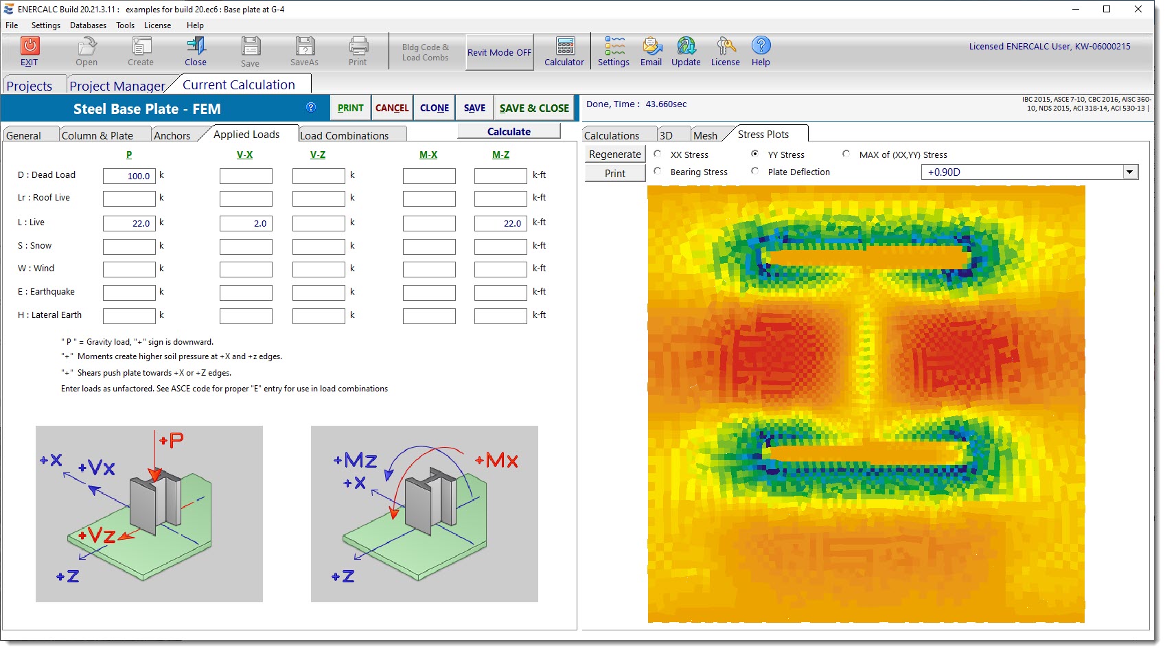
Stress Plots
The Stress Plots tab displays a variety of stress distributions using color rendering for the selected load combination.
•XX Stress displays the top/bottom flexural stress on the xx edge of each shell for the selected load combination. The xx edge is the edge that is generally parallel to the global Z axis (perpendicular to the global X axis).
•YY Stress displays the top/bottom flexural stress on the yy edge of each shell for the selected load combination. The yy edge is the edge that is generally parallel to the global X axis (perpendicular to the global Z axis).
•Max of XX, YY Stress displays the maximum of either the XX Stress or the YY Stress on every shell for the selected load combination.
•Bearing Stress displays the bearing stress distribution for the selected load combination. Note that this module uses compression-only springs to model the interface between the steel plate and the concrete support. So certain load combinations with significant moment may show large areas with no bearing stress. This signifies that the compression-only springs in that zone have been deactivated by the iterative solution process.
•Plate Deflection displays color gradients to represent the vertical displacement of the individual shells. Red represents downward displacement. Blue represents upward displacement.
 <
<