Stem Tab for Tapered Stem Retaining Wall |
  
|
Stem Tab for Tapered Stem Retaining Wall |
|
Tapered Stem Retaining Walls are cantilevered retaining walls where the soil face is battered to achieve a variable thickness from the base of the stem to the top of the stem.
When a Tapered Stem Retaining Wall is defined, the Stem tab will appear as shown below:
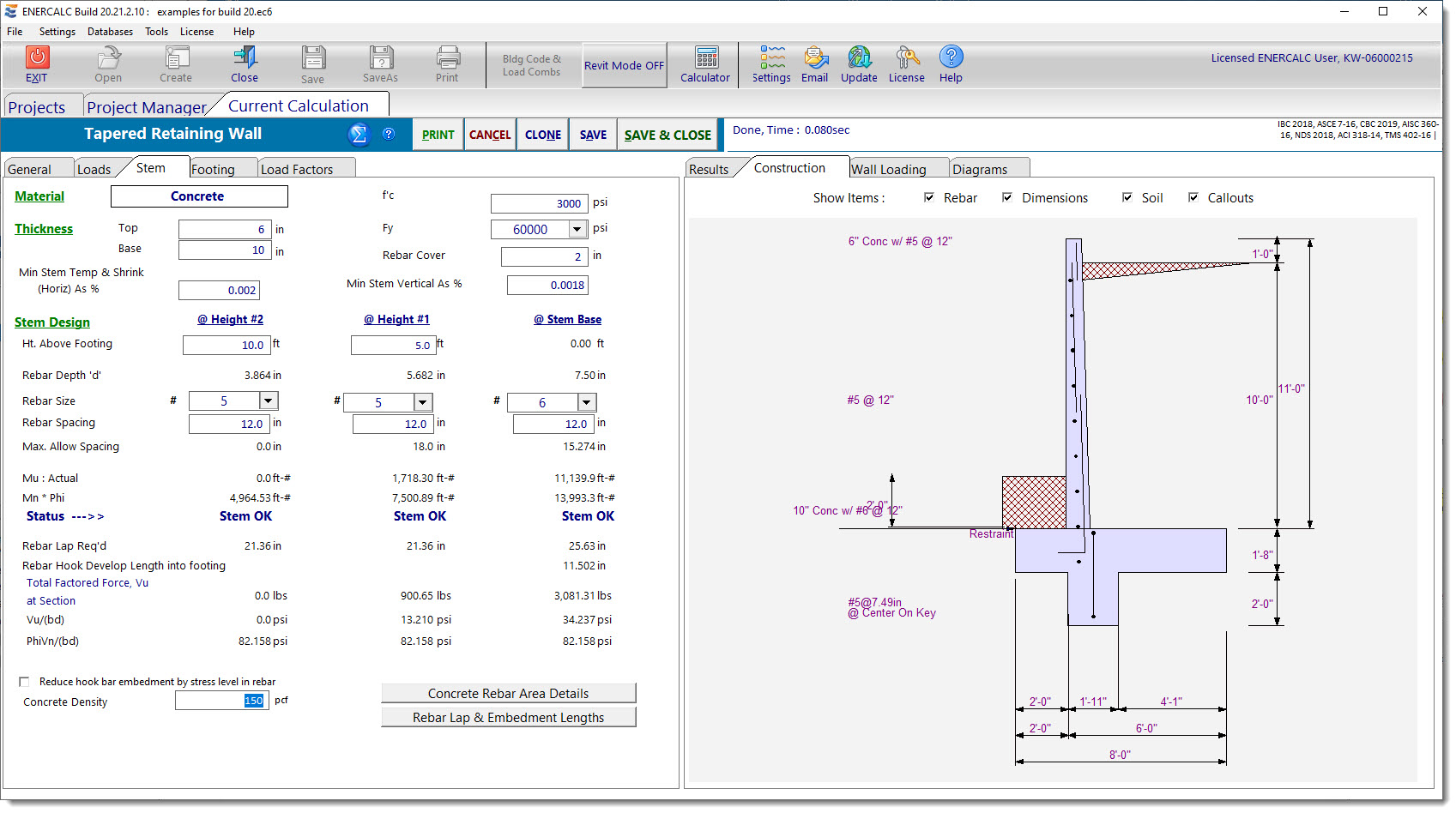
Note: Taper can only apply to the inside face (the face against the soil).
| Material: | The Material will automatically be defined as Concrete, since masonry cannot be tapered. |
| Thickness: | Top and Base: Enter the stem thickness at the top and at the bottom. |
| f’c and Fy: | Enter concrete strength and rebar yield stress. |
| Rebar Cover: | Select the rebar clear cover to consider in the design. |
| Stem Design: | Stem design will automatically be performed at the bottom of the stem (interface with the footing). In addition, you can specify two additional heights above the base to check moments and shears. These are identified as "@ Height #2" and "@ Height #1", where the latter is the lower height. |
| Ht. Above Footing: | Specify two heights above the top of footing elevation where a stem design should be performed (such as where it would be desirable to change the rebar pattern or size for economy). Height #2 is highest and Height at Stem Base will be fixed at 0.00. The #1 height should be located at a distance above the top of the footing that is at least equal to the lap splice length for the dowels. |
| Rebar Depth "d": | This will be computed based upon the heights you have chosen, the specified wall taper, and the specified Rebar Cover. The program automatically uses the specified clear cover and one-half of a bar diameter when determining "d". |
| Rebar Size: | Use the drop-down list box to select the desired rebar size. |
| Rebar Spacing: | Use the spinners to set the desired rebar spacing. (The maximum permissible spacing is 18 inches, which is in accordance with ACI.) |
Max. Permissible Spacing: This is the maximum permissible spacing for the rebar size selected. This is based on the strength calculation, but it will stop at an upper limit of 18 inches in accordance with ACI.
| Mu: | These are factored moments at the heights you have selected. These will be based on the load factors that you specify on the Load Factors tab. Compare these values with Design Moment as described below, to verify adequacy of your design at the selected height location. |
| ϕMn: | This is the design moment strength, which will be based upon the bar sizes and spacings you established, along with wall geometry, concrete strength, etc. |
| Status: | This indicates whether each stem design is OK at the specified height. If there is a problem, this will display a descriptive message such as "Mu > Phi * Mn" or "As < min" or "As > max" or "Ftg. Rebar Embed!". |
| Rebar Lap Req'd: | This is the lap splice length required based on the bar size used at the specified Design Height. It is the development length of the bar multiplied by 1.3 (assuming a Class B splice) and without adjustment for stress level. |
Rebar Hook Development Length into Footing:
This is the hooked development length that is required for the bar size specified at the stem base. It is based on the assumption that the bar is hooked into the footing with a 90° bend and minimum 12 db bar extension. The calculated values is also based on the assumption that the side cover (normal to the plane of the hook) is not less than 2.5 inches and that the cover on the extension beyond the hook is not less than 2 inches. These latter assumptions facilitate the application of a factor of 0.7 to the calculated value of ldh.
| Shear at Section: | This is the total factored shear at the indicated height. |
| Vu: | Factored shear stress at designated height computed by Shear at Section / (12 * "d"). |
| ϕVn: | For concrete designed per ACI 318-14 and earlier, the nominal shear strength is 2*λ*sqrt(f'c). |
| For concrete designed per ACI 318-19, the nominal shear strength is per the one-way shear strength provisions of §22.5 and Table 22.5.5.1 (as referenced by §13.3.6.1 and §7.5.3.1). Concrete stems are assumed to be unreinforced for out-of-plane shear. Therefore, Av is less than Av,min, and equations (a) and (b) from Table 22.5.5.1 need not be considered. |
| Option to reduce hooked bar embedment depth: | When the checkbox is checked the program will reduce the hooked embedment depth by the considering the ratio of (As required)/(As provided). |
| Concrete Density: | Use the spinners to set the unit weight of the concrete. |
 <
<