General Section Property Calculator |
  
|
General Section Property Calculator |
|
Overview
This module determines section properties for built-up sections with rectangles, hollow circles, solid circles, standard AISC steel sections and general multi-sided solid shapes.
AISC sections can be recalled from the database files and can be included in the built-up section. All sections from the 13th Edition AISC Steel Construction Manual are available, and can be reoriented as necessary.
The calculated section property values include: area, moments of inertia, center of gravity location, extreme fiber distances, section moduli, and radius of gyration.
Basic Usage
•Before starting data entry, be sure you have set up an X-Y coordinate system to consistently reference all component locations.
•For each rectangular shape, enter the height, width, and center of area measured from the datum.
•Hollow circular sections are entered by specifying the outside radius and thickness. Solid circular sections are entered by specifying the outside radius and setting the thickness to zero.
•For AISC sections, you can use the Xcg and Ycg input fields to locate the section's centroid position with respect to the datum. The module knows the centroid location of AISC members with respect to their own extreme fiber locations. However, you need to enter the location of the member's centroid in relation to the other members in the built-up section. Be careful, as this can be tricky when entering channels, angles, and tee sections that are rotated.
•A unique feature allows the user to specify that AISC sections can be rotated in one-degree increments, steel angle sections can also be mirrored about their Y axis, and the entire built-up section can be rotated to any desired angle.
Assumptions & Limitations
The module operates on a simple calculation procedure:
•Calculate the moment of inertia of each shape,
•Calculate the neutral axis of the group of shapes, and
•Calculate the moment of inertia of the group using I + A*D2 equations.
More complex analysis such as polar moment of inertia, plastic moduli, and buckling constants are beyond the scope of the module at this time but continuing development will add these items in future updates.
Rolled Section / Table
This tab enables you to specify up to 10 sections from the AISC Edition database to use in a built-up member.
The square buttons across the top of the tab are used to represent the component sections that comprise your built-up shape. When a section has been specified for a particular button, a small green upward facing triangle will be shown under the corresponding button. Click on any button to add a section or view and modify the section that has already been assigned to that button.
Note: It is important to understand that the numbered buttons on the various tabs DO NOT represent different built-up shapes. Instead, each instance of this module only creates ONE built-up shape, and the overall built-up shape consists of a composite of ALL sections that currently exist on ANY buttons in the Rolled Section / Table tab, the Rectangular & Circular tab, and the General Shapes tab.
To insert an AISC section you can:
•Type in the section name and press [Tab]. The module will search the database and retrieve the information.
•Use the [Browse Steel Sections] button to display the steel database where you can navigate and select the desired section.
Rotation Angle: Counter-Clockwise
If you need to rotate a section, click one of the four angular rotation buttons.
Rotate Section 180 degrees about its own y-y Axis
This checkbox option will only be displayed for single-angle sections. It offers the ability to mirror a single-angle section if needed.
Xcg & Ycg
Enter the location of the section's centroidal axis measured from the datum (the origin of your assumed X-Y Cartesian coordinate system).
Section Properties
These values will be filled in after you make your choice from the AISC database. HOWEVER you can alter these values yourself. Of particular importance for unsymmetrical sections is entering the correct "Xbar" and "Ybar" location. This is the distance from the lower-left edge of the section, measured upwards and to the right, to the centroidal axis position of the section.
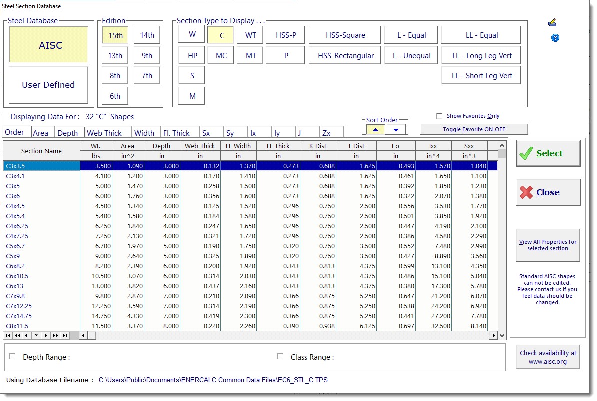
Steel Section Database
Click the [Browse Steel Sections] button to display the AISC database window:
Rectangular & Circular
This tab allows you to specify simple rectangular and circular shapes.
The square buttons across the top of the tab are used to represent the component sections that comprise your built-up shape. When a section has been specified for a particular button, a small green upward facing triangle will be shown under the corresponding button. Click on any button to add a section or view and modify the section that has already been assigned to that button.
Not Used / Rectangular / Circular
Select the shape you wish to use for this item.
Rectangular Data Entry
When a rectangular shape is chosen the data entry consists of height and width.
Circular Data Entry
When a circular shape is selected the data entry consists of Outside Radius and Wall Thickness (not inside radius). To model a solid circular section, enter the appropriate Outside Radius and set the Wall Thickness to zero.
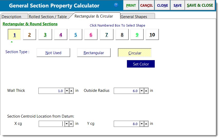
Xcg & Ycg
Enter the location of the section's centroidal axis measured from the datum (the origin of your assumed X-Y Cartesian coordinate system).
General Shapes
This tab allows you to select from a number of common polygonal shapes. With each selection the reference drawing and data entry prompts will change.
The square buttons across the top of the tab are used to represent the component sections that comprise your built-up shape. When a section has been specified for a particular button, a small green upward facing triangle will be shown under the corresponding button. Click on any button to add a section or view and modify the section that has already been assigned to that button.
Xcg & Ycg
Enter the location of the section's centroidal axis measured from the datum (the origin of your assumed X-Y Cartesian coordinate system).
Rotation Angle: Counter-Clockwise
For these shapes you can rotate the section in one-degree increments. Positive angles represent counter-clockwise rotation.
Calculations
Detailed Properties Table
This table summarizes each of the component items you have added to the section. It reports their individual locations, properties and maximum distance from CG for each of the four edges.
Note: This table scrolls to the right. Just use the scroll bar along the bottom of the table.
Total Area
The total area of all defined shapes, including the area of any AISC sections which have been included in the built-up shape.
Inertia: Ixx & Iyy
The overall moment of inertia of the composite section is determined by applying the following equation to all the defined shapes:
Ixx = Iox + (A * dy2) and Iyy = Ioy + (A * dx2)
where d = Distance from the shape's C.G. to the overall C.G. of the composite section, measured in the direction indicated by the subscript.
Section Modulus: Sxx and Syy
These values are the calculated section moduli of the composite section. The values are determined by dividing Ixx or Iyy by the extreme fiber distances above, below, right, and left of the center of gravity of the section.
Radius of Gyration
The radius of gyration of the composite section is determined using the typical equation: rxx = (Ixx/A)½ and ryy = (Iyy/A)½.
Max Distance from CG
For each of the sections in the built-up shape, these columns report the distance from the extreme fibers of that section to the C.G. of the composite section.
Sketch
 <
<