Displaying Diagrams |
  
|
Displaying Diagrams |
|
In addition to the Sketch of the beam, we can also display several types of diagrams. Selecting the Diagram tab will display the Shear/Moment/Deflection diagram as shown below:
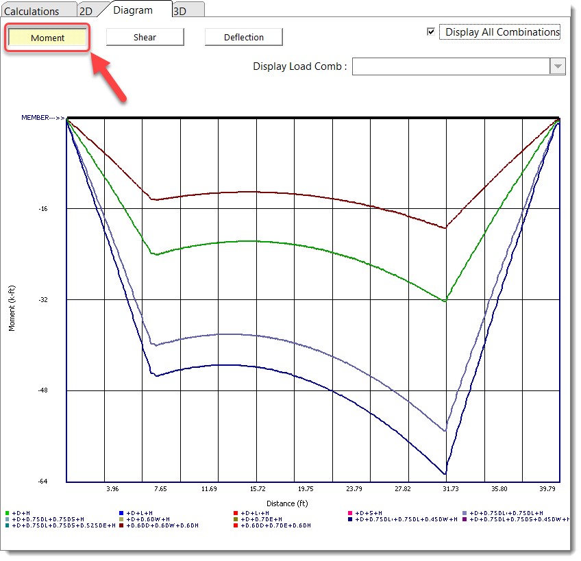
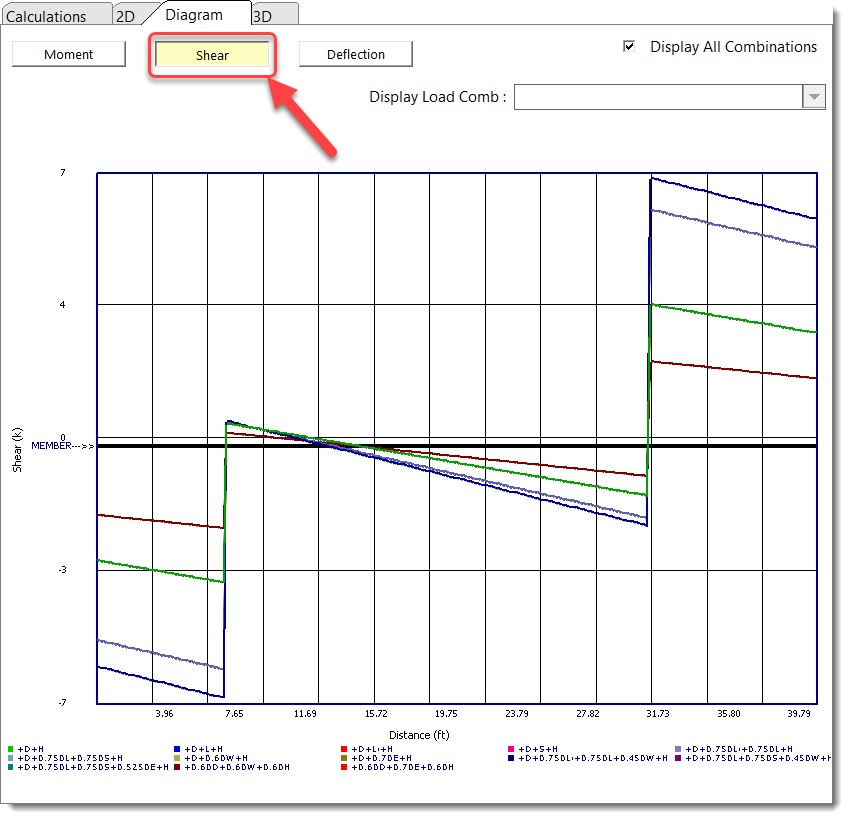
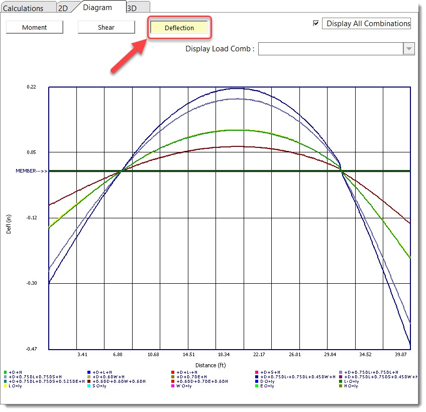
Of special interest are the various load combinations that can be viewed. By selecting the desired load combination here you can view the detailed shear/moment/deflection variations produced by each combination.
Note: In the previous steps, we turned on the option to have the program automatically handle unbalanced Live load placement. While this is a helpful feature for design, it tends to produce an abundance of results. If you'd like to simplify the view of shear, moment, and deflection diagrams, click the Span Loads tab and temporarily turn off the option to have the program automatically perform unbalanced Live load placement. To view even more specific diagrams, deselect the option to Display All Combinations, and then select the load combination of interest in the dropdown list box.
 <
<