Pole Footing Embedded in Soil |
  
|
Pole Footing Embedded in Soil |
|
This module determines actual soil pressures and required depths for pole footings primarily supporting lateral loads.
Such footings are commonly called "flagpole footings".
Since applied top moment generates lateral soil pressures that usually govern the design, these footings typically have a depth/width ratio of 2:1 and greater.
Cases with and without lateral restraint at the ground surface are allowed. Evaluation of actual and allowable pressures is in accordance with the IBC Section entitled "Embedded posts and poles".
General
Pole Footing Shape
Use this section to specify whether the pole is round or rectangular (assumed square).
Footing Width/Diameter
Enter the width or diameter of the pole footing. Width is measured perpendicular to force direction. If the pole is specified as square, the module will multiply the value entered for footing width 1.41 to determine an equivalent width dimension for calculations.
Restraint at Ground Surface
Specify whether the footing is free at the ground surface or restrained and cannot translate. A restrained footing indicates that a concrete slab or other rigid element prevents translation of the pole footing at the ground surface, but does not prevent rotation. When specifying a restrained footing, you must assure yourself that the final force required to provide the restraint can actually be developed by the restraining construction.
When ground surface restraint is present, the lateral pressure value at the bottom of the pole will govern the design.
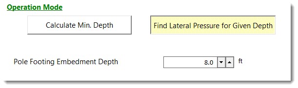
Operation Mode
This setting provides an option to select from two different modes of operation as follows:
Calculate Minimum Depth: In this mode, the module will iterate to determine the minimum embedment depth required to make the actual lateral soil pressure lower than the allowable soil pressure.
Find Lateral Pressure for Given Depth: In this mode, the module will calculate the lateral earth pressures caused by the specified pole size, embedment depth and applied loads. When this option is selected, a Pole Footing Embedment Depth input field will appear as shown below:
Allowable Pressure Limit
Two options are provided as indicated below:
Limit only by "Max. Passive": Solves for a design that allows the passive pressure to approach the value specified in the Allowable Lateral Passive Pressure field below (limited to the value specified in the Maximum Lateral Pressure Limit field).
Example: Assume allowable lateral passive pressure is 200 psf/ft with an upper limit of 3000 psf.
When the Limit only by "Max. Passive" option is selected, the solution will progress as follows:
•The program will start with a shallow assumed depth and calculate the 1/3 embedment depth.
•Then it will calculate an allowable lateral passive pressure for that 1/3 embedment depth.
•Next, the program will compare this calculated allowable lateral passive pressure value to the specified upper limit on the allowable passive pressure and select the smaller of the two.
•The IBC formula is then used to determine the actual pressure for the assumed embedment depth.
•If the actual pressure is higher than the allowable pressure, the program increments the length and repeats the above process.
•For illustration, assume that the iterations have progressed to the point where the embedment depth is now 42 feet.
•The program will calculate the 1/3 embedment depth as (42 feet / 3) = 14 feet.
•Then it will calculate an allowable lateral passive pressure of (200 psf/ft * 14 ft) = 2800 psf.
•Next, the program will compare this calculated allowable lateral passive pressure value to the specified upper limit on the allowable passive pressure and determine that 2800 psf < 3000 psf, therefore it will use 2800 psf as the Allowable Lateral Passive Pressure.
•When the program finds an embedment depth for which the actual pressure is lower than the allowable pressure, it rounds the embedment depth up slightly and reports that value.
Use limit of 12 ft (per IBC): Solves for a design that achieves a passive pressure that does not exceed the Allowable Lateral Passive Pressure, where the Allowable Lateral Passive Pressure is calculated based on 1/3 of the embedment depth but not to exceed 12 feet (and limited to the value specified in the Maximum Lateral Pressure Limit field).
Example: Assume allowable lateral passive pressure is 200 psf/ft with an upper limit of 3000 psf.
When the Use limit of 12 ft (per IBC) option is selected, the solution will progress as follows:
•The program will start with a shallow assumed depth and calculate the 1/3 embedment depth.
•Next, it will compare the 1/3 embedment depth to 12 feet and base the allowable lateral passive pressure calculation on the smaller of the two.
•Next, the program will compare this calculated allowable lateral passive pressure value to the specified upper limit on the allowable passive pressure and select the smaller of the two.
•The IBC formula is then used to determine the actual pressure for the assumed embedment depth.
•If the actual pressure is higher than the allowable pressure, the program increments the length and repeats the above process.
•For illustration, assume that the iterations have progressed to the point where the embedment depth is now 42 feet.
•The program will calculate the 1/3 embedment depth as (42 feet / 3) = 14 feet.
•Next, it will compare the 1/3 embedment depth to 12 feet and determine that 14 feet > 12 feet, therefore it will base the allowable lateral passive pressure calculation on 12 feet.
•Then it will calculate an allowable lateral passive pressure of (200 psf/ft * 12 ft) = 2400 psf.
•Next, the program will compare this calculated allowable lateral passive pressure value to the specified upper limit on the allowable passive pressure and determine that 2400 psf < 3000 psf, therefore it will use 2400 psf as the Allowable Lateral Passive Pressure.
•When the program finds an embedment depth for which the actual pressure is lower than the allowable pressure, it rounds the embedment depth up slightly and reports that value.
Allowable Lateral Passive Pressure
The allowable lateral passive pressure that the soil can withstand. This value is entered as pounds per square foot per foot of embedment depth.
Maximum Lateral Pressure Limit
This value is used to specify an upper limit on the Allowable Lateral Passive Pressure, so that it does not increase in an uncontrolled manner as the embedment depth increases. This value is entered as pounds per square foot.
Applied Loads
This module allows many types of loads to be applied to a pole footing embedded in soil.
Lateral Concentrated Loads
Module allows one concentrated load with various load types to be applied at a specified distance above the surface of the soil.
Lateral Distributed Loads
You can apply a uniform lateral load to the pole by specifying the magnitude of the load and the starting and ending locations.
Applied Moments (Only displayed when restraint at ground surface exists)
You can apply a concentrated moment. No "height" entry is required, because it is purely a rotational force.
Vertical Load
You can also apply a vertical load so that the module can calculate the vertical bearing load on the footing for each load combination.
Load Combinations
Use this tab to specify the load combinations you want the module to analyze.
Calculations
The calculations tab provides a summary of the results.
The table reports the resulting forces, moments and required depth for each load combination.
The Controlling Values area provides information for the most severe load combination.
2D Sketch
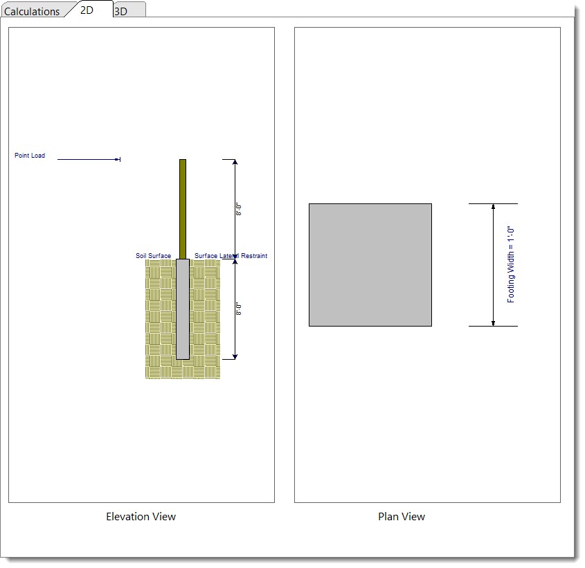
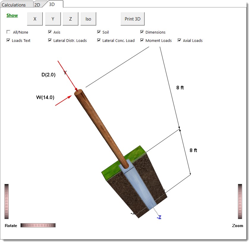
3D Rendering
 <
<