This module calculates the capacity of an unreinforced concrete slab to support isolated concentrated loads. Typical use is for legs of storage racks not supported by a building structure, and is not within the scope of the ACI code.
The design method is based on the recent research of Shentu, Jiang and Hsu. For further information see (1) "Load carrying capacity for concrete slabs on grade" in the ASCE Journal of Structural Engineering January 1997; (2) Acceptable Design & Analysis methods for use of slabs-on-grade foundations, City of Los Angeles LAMC91.1806 and (3) Seismic considerations for steel storage racks, FEMA 460 September 2005.
The work of Shentu and colleagues has shown that load carrying capacity, verified with test results, can be very closely predicted using the formulas given below.
Rather than historical elastic methods, the method used here is elasto-plastic which is more applicable to ultimate capacity determination.
Allowable load capacity is given by this equation:
Pn = 1.72 [(ks R1 / Ec) 10,000 + 3.60] * ft' * d2
Where
ks is the modulus of subgrade reaction of the soil, pci
R1 is sqrt(Plate Width * Plate Length) / 2, inches
Ec is the concrete elastic modulus, psi
ft' is the tensile strength of the concrete = 7.5 sqrt(f'c), psi
d is the slab thickness, inches
The above equation assumes that the load acting on the slab is unique and no other nearby loads are affecting the calculation.
To assist in the evaluation of slabs-on-grade, this module also provides a calculation of the distance that the closest load may be without affecting the calculated slab capacity. The calculation given below is based on research of Packard, Pickett & Ray and more recently by Spears and Panarese. It is also discussed in ACI 360R-92(4).
In this module the distance is calculated as 1.5 * "Radius of Relative Stiffness" given by the following equation:
b = [ Ec d3 / (12 * (1-u2) * ks)] 0.25
Where
b is the radius of relative stiffness
Ec is the concrete elastic modulus, psi
d is the slab thickness, inches
u is Poisson's ratio which is set to 0.15 in this module
ks is the modulus of subgrade reaction of the soil, pci
Additionally this module allows the user to enter a Factor of Safety that is used when the module reports the adequacy of each applied load.
General

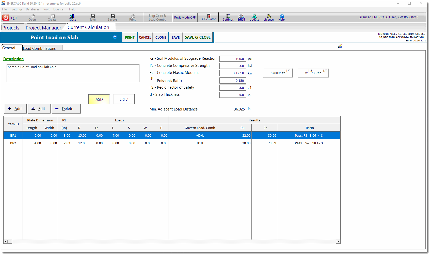
This module is designed to allow the user to create a table of loads applied to a particular concrete slab and supporting soil with one set of material properties.
You can then use the [Add], [Edit] and [Delete] buttons to add a set of applied loads and base plate dimensions. From this data all load combinations are used to determine the maximum axial force. For the plate dimension you specify, the maximum load capacity for the point load application is calculated and compared with your required factor of safety.
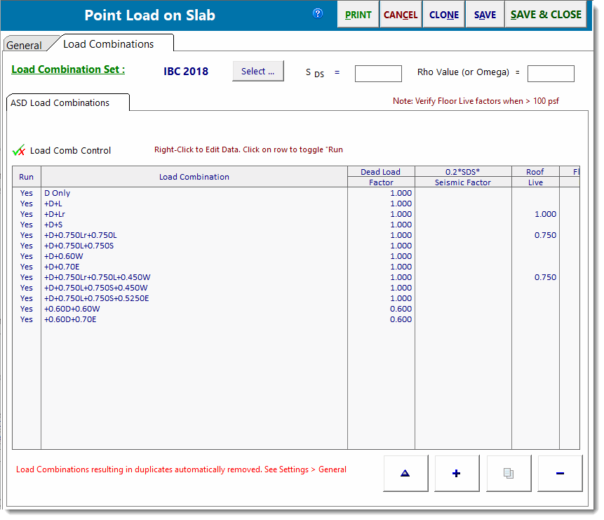
The option for ASD or LRFD analysis only changes the load combination set used. Because this is a non-ACI design process, you need to enter a Factor of Safety to determine the final design status. Research material suggests a F.S. of 3.0.
The only item that may not be self-explanatory is R1, which is sqrt(Plate Width * Plate Length) / 2 in units of inches.
Load Combinations
