Pile Group Analysis |
  
|
Pile Group Analysis |
|
This module considers a concentrated load applied to a rigid pile cap and distributes it to a group of piles.
Force distribution is performed assuming a rigid pile cap and that all piles have equal vertical load resistance. Distribution of loads to each pile due to the effect of load eccentricity is determined using a skew bending analysis. This considers simultaneous action about both X and Y axes. The module is also an efficient method for determining loads on a pile group in the as-driven arrangement.
General
NOTE! Establish an X & Y Coordinate system prior to entering pile and load locations. Module requires a 2-dimensional pile group to be defined. It will not report results for a collinear group, i.e. a single line of piles.
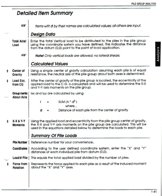
Total Applied Axial Load
Enter the total vertical load to be distributed to the piles in the pile group using the coordinate system you have defined.
Note: Only vertical loads are allowed; no lateral shears.
X & Y Distance to Load
Enter the distance from the X & Y datum (0,0) to the location of the applied vertical load.
Number of Piles
This entry defines the number of piles in the group. As you change the number of piles, the number of data entry locations will match the specified number of piles.
Pile Locations: distance from Datum to the pile
Enter the distance from the X & Y datum (0,0) to the center of each pile location.
Load Combination to use
This selection will switch the load combinations shown on the Load Combinations tab between Service and Factored design combinations.
Load Combinations
This tab allows you to specify the load combinations to be considered.
Results
This tab summarizes the overall calculated values for the pile group and lists the maximum factored load for each pile and the load combination that produced the maximum load.
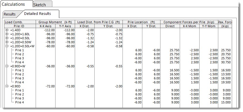
Detailed Results
This tab gives the detailed calculations for each pile for each load combination. It indicates the Direct force as well as the component of axial load that is due to the net moment applied to the entire group. This latter effect will be observed for any pile that is located at a distance from the center of gravity of the pile group.
2D Sketch
Design Basis:

 <
<