Methodology / Analysis & Design Assumptions |
  
|
Methodology / Analysis & Design Assumptions |
|
References used for the development of this program are listed in Appendix E.
A basic design requires these steps:
There are many theories presented for calculating embedment depths (Plum method and others) and that shown in figure below is one that closely agrees with other methods.
Determine the driving forces, that is, forces imposed by any construction surcharges and the active soil pressure tributary to each pile beam. Use the Rankine equation to calculate Ka. Several designs may be done to optimize the beam spacing based upon lagging selection, embedment depths, and beam sizes.
Referring to the figure below, after Pa and Pv, have been calculated, the depth of embedment must be determined. This will be a function of the allowable passive pressure and arching factor allowed to increase the effective flange width, or hole diameter if pre-drilling is used. The arching factor. A. can be taken as 0.08 * phi, but should not exceed about 2.5. This means that the effective pressure width in front of a 24" diameter drilled and concrete filled beam encasement, with a phi of 32° would be 0.08 * 32 = 2.56. but use 2.5. Thus the effective passive pressure would be a width of 2.0*2.5 = 5.00 feet which will considerably reduce embedment depth and moment applied to the beam.
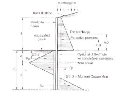
Figure illustrates theorized forces on cantilevered soldier beam in sandy soil
For determining the embedment depth to zero shear (where beam bending is maximum), designated "d", the following equation can be used:
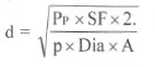
Where Pp is equal to and counteracting to Pw + Pa; SF is the safety factor applied to allowable passive pressure; A is the arching factor multiplier; Dia is the hole diameter or flange width, whichever applicable; and p is the allowable passive pressure in pcf at “d".
1. The maximum beam moment is then determined by summing moments above the point of zero shear. Mathematically the result is equivalent to:
Mmax = Pw (0.50H + 0.67d) + Pa (0.33H + 0.67d)
2. The maximum moment is resisted by a passive pressure couple consisting of Fp * 0.67D. Therefore the required depth D can be estimated from the following equation:
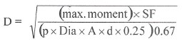
The required depth of embedment is then (d + D). As a rule-of-thumb for sandy soils this is usually in the range of 1.3 H to 1.5 H. It is conservative to add 20% - 30% depth to calculated embedment.
3.After the maximum moment has been computed, convert it to LRFD (Load Resistance Factor Design) by multiplying by the usually applicable load factor of 1.6. Then select several beam options from AISC latest edition, LRFD Steel Design Handbook.
4.Select the lagging. Treated lumber should be used. Calculate the lateral pressure at various depths, Hy,(to determine changing lagging thicknesses) which is Ka * Soil Density * Hy. When the simple span moment is calculated it is common to multiply by 0.8 because of arching action of the soil between pile beams. Lagging is typically either 3" or 4" by 12” treated wood. Lagging ends should bear against the beam flange a minimum of 3". Allow about 1" between each lagging for drainage.
In addition, it is important to understand that the tied-back version of the module is based on a stiffness analysis from the 2D Frame module within ENERCALC SEL. It uses beam elements spanning from the top of the retained height to the top tie-back, which is modeled as a lateral support. If there is more than one tieback, the subsequent tie-backs are modeled as lateral supports. The lowest beam segment spans from the lowest tie-back to a "base" node that is modeled at the bottom of the embedment depth.
The top node is free to rotate and deflect. Nodes representing tie-backs are free to rotate and deflect vertically, but are constrained laterally. The "base" node cannot translate at all, but the user can specify whether it is able to rotate or if it should be treated as rotationally fixed.
The applied loading is as shown on the Soil Pressure Reference tab.
Reactions and displacements are reported by the solver. The user will probably need to increment the embedment depth until the module reports that the embedment is acceptable for the modeled conditions.
Steel design is performed at many increments along the length of the pile, taking into consideration the steel yield strength, the section forces, and the bracing assumptions specified by the user.
 <
<