Steel Member Design Criteria |
  
|
Steel Member Design Criteria |
|
Steel Design > Steel Design Criteria > Steel Member Design Criteria prompts you with the following dialog.
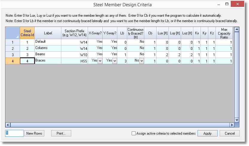
It allows you to define and assign design criteria for members.
An ID is assigned automatically to each design criterion by the program and may not be changed. You may assign a label with 127 maximum characters to each design criterion.
The column design criteria include:
•Section Prefix, which is a comma delimited list. For example, if you want the member section to be with W10 or W12 size, enter the prefix as “w10,w12”. You also specify the prefix as the exact AISC shapes. Use the prefix “Default” if you do not want the member section changed from the original shape.
•Sway flags in x and y directions.
•The length between points that are braced against lateral displacement of compression flange Lb. Currently, the program only supports equal Lb along the member length. For non-continuously braced, the program will use the member length for Lb if the value is entered 0. For continuously braced, 0 must be entered for Lb.
•Lateral-torsional buckling modification factor for nonuniform moment diagrams Cb. The program will automatically calculate Cb if the value is entered 0. You can always use Cb = 1.0 for conservative reasons.
•Unbraced lengths in x, y and z directions. You may enter zero if you want the program to use the member lengths as the unbraced lengths.
•Effective length factors in x, y and z directions.
•You have the option to set the maximum capacity ratio. By default, this ratio is 1.0. You can set a value less than 1.0 (but greater than 0.0) for conservative reasons.
 <
<