General Footing by FEM |
  
|
General Footing by FEM |
|
The General Footing by FEM module is useful for footings of a variety of shapes and supporting up to five pedestals.
The module gathers geometric info, soil properties, and loading data, and then generates a finite element model that is analyzed behind the scenes in ENERCALC 3D. The results are then passed back to the module for review and refinement.
This process allows for considerably more flexibility than some of the other footing modules. For example, this module supports many common shapes of footings. It also allows square, rectangular and round pedestals to be modeled, and the square and rectangular pedestals can even be rotated. A full biaxial analysis is performed using compression-only springs for each load combination, including service-level combinations for soil pressure evaluation and stability checks, and strength-level combinations for concrete design.
The module allows the user to control the mesh density, and to review the resulting mesh that is automatically created prior to running the analysis. It also offers two options for the stiffness of the footing. One option is to use the calculated stiffness based on material properties, thickness, and specified cracking factors. A second option is to consider the footing as a "Rigid Body", which evaluates the footing as if it was an infinitely stiff plate.
General Tab
Concrete & Rebar Properties
Enter material properties and design parameters. Note that code modifications for lightweight concrete are not applied in this module. The purpose of this input is mainly to allow the user to specify something in the range of 145 to 150 pcf.
Stability Settings
Set minimum allowable factors of safety for sliding and overturning checks.
Soil Design Values
Specify allowable soil bearing pressure, subgrade modulus, soil density, coefficient of friction and passive pressure.
Footing Tab
Footing Shape
Select the desired footing shape and specify the data necessary to define the plan dimensions of the footing.
Suggested Footing Target Element Size
The module suggests a value to be used as the Footing Target Element Size. The value generally represents one-fiftieth of the longest dimension of the footing.
Footing Target Element Size
This field is used to specify the desired target size of the finite elements that will be used to model the footing. Note that this input is specified in units of inches, and that this is only a target size. The meshing procedure will attempt to achieve this size for as many elements as possible, but it is not a rule or a limit. The smaller the target element size, the larger the model (roughly a squared function).
Footing Thickness
Specify the thickness of the footing in units of inches.
Footing Stiffness
This section offers two options. The first is to treat the footing as a rigid body. The second is to consider the actual stiffness of the footing based on thickness, material properties, and the specified cracking factor.
Pedestals & Applied Loads Tab
Pedestal Selection
Click the desired button to enter geometric and loading data for a particular pedestal. Up to five pedestals can be specified per footing.
Description
The description field is available for a text description of each individual pedestal.
Shape
The shape dropdown list box offers Unused, Square, Rectangular and Round. Dimension fields are displayed based on the selected shape. Note that pedestal dimensions are always collected in units of inches, even if the "pedestal" is long, like a wall. Enter the Pedestal Height (in inches) above the top of the footing.
Pedestal Centroid to Footing Datum
This area collects dimensions to locate the centroid of the pedestal. Note that dimensions are in units of feet, and that the pedestal outline is visible on the Mesh Plot for reference.
Punching Shear Perimeter Adjustment Factor
This factor acts as a multiplier on the calculated punching perimeter. The punching perimeter is calculated as follows:
•Square Pedestal: 4 * (d/2 + Pedestal dim + d/2)
•Rectangular Pedestal: 2 * [(d/2 + Pedestal X dim + d/2) + (d/2 + Pedestal Z dim + d/2)]
•Round Pedestal: pi * (d/2 + diameter + d/2)
So by applying the Punching Shear Perimeter Adjustment Factor to the calculated punching perimeter, it is possible to account for situations where the punching perimeter falls partially outside the footing, such as in corner and edge conditions. Note that this factor is separate and distinct from the Punching Alpha s Factor described in the next section. For example, if it is determined that only three quarters of the calculated punching perimeter actually falls within the footprint of the footing for a particular corner or edge column, then the Punching Shear Perimeter Adjustment Factor can be specified as 0.75 for that column.
Note that the module collects clear cover, not an actual value of d. And the size of the bars is not known. So the program makes an allowance of 1/2 inch for the rebar radius when calculating d. The value of d is calculated as Footing Thickness minus clear cover minus an additional one-half inch to account for the radius of the rebar.
Punching Alpha s Factor
Based on the position of a pedestal (interior, edge, or corner), ACI requires the use of a specific value for the Alpha s factor: 40, 30 or 20 respectively.
CW Rotation
This field allows square and rectangular pedestals to be rotated by a specified number of degrees. Positive = CW. Negative = CCW.
Loads
Loads can be specified for each of the primary load types. Positive values of Py act downward. Positive Mxx and Mzz tend to create higher soil pressure on the positive X and positive Z sides of the footing, respectively. Positive Vx and positive Vz act in the positive X and positive Z directions, respectively. Moment and shear can be defined with respect to the footing axis system or the pedestal axis system. Overburden DL can be specified over the entire footing. It can also be omitted at the footprint of pedestals.
Loading is facilitated by the fact that the module allows up to four independent wind load cases and four independent seismic load cases for each model. This means that one calculation can include cases such as:
1.Net wind to the East,
2.Net wind to the West,
3.Net wind to the North, and
4.Net wind to the South.
It could also be set up to run:
1.Net wind in the East-West direction with positive internal pressure,
2.Net wind in the East-West direction with negative internal pressure,
3.Net wind in the North-South direction with positive internal pressure, and
4.Net wind in the North-South direction with negative internal pressure.
Likewise, this increased loading capacity means that a single calculation could include seismic load cases such as:
1.Seismic in the East-West direction with positive eccentricity,
2.Seismic in the East-West direction with negative eccentricity,
3.Seismic in the North-South direction with positive eccentricity, and
4.Seismic in the North-South direction with negative eccentricity.
It could also be set up to run:
1.100% Seismic in the East-West direction with a concurrent 30% seismic to the North,
2.100% Seismic in the East-West direction with a concurrent 30% seismic to the South,
3.100% Seismic in the North-South direction with a concurrent 30% seismic to the East, and
4.100% Seismic in the North-South direction with a concurrent 30% seismic to the West.
Note: Footing self-weight is applied automatically as Dead Load. Pedestal self-weight is not automatically accounted for.
Suggested Target Mesh Element Size
The module suggests a value to be used as the Target Mesh Element Size at the pedestal footprint.
Footing Target Element Size
This field is used to specify the desired target mesh element size of the finite elements that will be used to model the footing within the footprint of the selected pedestal. Note that this input is specified in units of inches, and that this is only a target size. The meshing procedure will attempt to achieve this size for as many elements as possible, but it is not a rule or a limit. The smaller the target element size, the larger the model (roughly a squared function).
Load Combinations Tab
Select the desired load combination set with the Select button. Specify Sds and Rho values to be incorporated into the generated load combinations if desired. Combination sets are automatically generated for strength-level (concrete design), and service-level (soil pressure, sliding, overturning). Each load combination in each set can be individually modified and/or turned on or off as desired.
Calculations Tab
Results
Displays a summary of failure modes, factors of safety or utilization ratios, design values, and governing load combinations.
Soil Pressure
Reports the maximum soil pressure and associated load combination, as well as soil pressures for each shell for each load combination.
Settlement
Reports the maximum settlement and associated load combination, as well as settlement for each node for each load combination.
Actual Mu & Vu
Reports the maximum Mxx, Myy, Vxx and Vyy with associated load combinations, as well as values of Mxx, Myy, Vxx and Vyy for each shell for each load combination.
Wood-Armer Results
Reports envelope results of Wood-Armer moments and required areas of steel for the top surface and the bottom surface at each edge of each shell.
Technical Note:
The General Footing x FEM module uses ENERCALC 3D as the underlying solver.
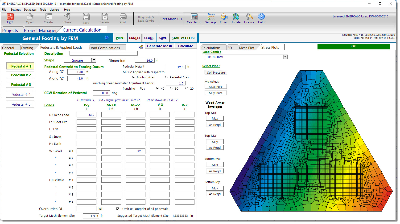
ENERCALC 3D refers to shell edges as follows. The X edge of the shell is the edge that the local X axis protrudes through, and the Y edge of the shell is the edge that the local Y axis protrudes through.
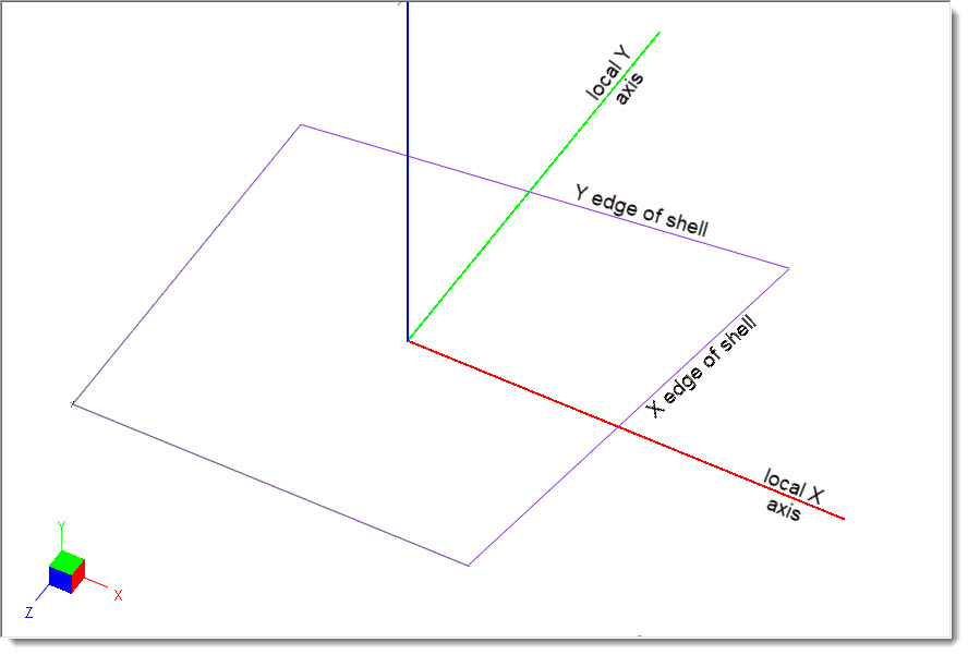
When ENERCALC 3D refers to shell moments, it uses the following convention. Mx represents the moment on the X edge of the shell, and My represents the moment on the Y edge of the shell.
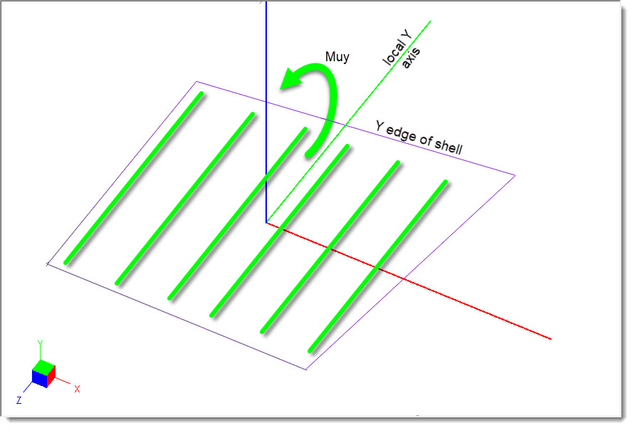
The General Footing by FEM module automatically orients all shells so that their local X axis coincides with the global X axis (both in direction and in algebraic sense). Following the right-hand rule, this also means that the local Y axis is parallel to the global Z axis, and the positive sense of the local Y axis points in the opposite direction from the positive sense of the global Z axis, as shown in the image above.
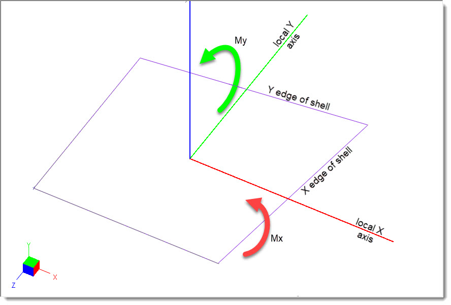
Wood-Armer moments Mux are not moments about the global X axis. Instead, they act on the X edge of the shell, meaning that they would be resisted by reinforcing steel placed parallel to the global X axis (perpendicular to the global Z axis), as shown below.
Likewise, Wood-Armer moments Muy act on the Y edge of the shell, meaning that they act about the local and global X axis, and would be resisted by reinforcing steel placed parallel to the local y (global Z) axis, as shown below.
Overturning
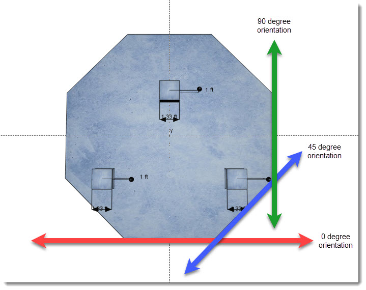
Reports the overall overturning stability ratio and the associated load combination and orientation of the overturning axis. Also reports the controlling overturning ratio for each load combination, including the overturning moment, the resisting moment, and the orientation of the overturning axis.
Overturning is evaluated about many axes starting with the axis oriented at zero degrees, represented by the red line in the screen capture below. The blue line represents a CCW orientation of 45 degrees. Green represents the 90 degree orientation, etc.
Sliding
Reports the lowest sliding ratio and the associated load combination. Also reports the sliding ratio for each load combination, including the vertical load, friction coefficient, sliding resistance, and applied force.
Punching
Reports the punching shear and resistance.
Shell Info
Reports the area and bounding node info for each shell in the model.
3D Tab
Displays a 3D rendering of the footing. Display options allow control over the individual elements to be shown.
Mesh Plot Tab
Displays a graphical depiction of the underlying finite element model mesh. Click the Regenerate button to refresh the mesh display.
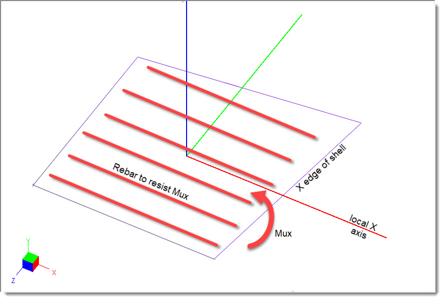
Stress Plots Tab
Displays plots that graphically depict soil pressure, pure flexural moments, Wood-Armer design moments, and area of steel required to satisfy Wood-Armer moments.
 <
<