Masonry Shear Wall |
  
|
Masonry Shear Wall |
|
General
This module allows the design of masonry shear walls including multi-story walls with no openings but with up to five levels of differing length, height, thickness, grouting and reinforcing patterns.
The wall will be composed of two zones:
Chord Zone: The areas at both ends of each level that contain chord rebar in every cell. (Always solid grouted.)
Field of Wall: The area between chord zones that may have a different reinforcing/grouting pattern. (May be partially-grouted or solid-grouted.)
Convenience Features
The module collects data on a level-by-level basis to allow the user to account for varying reinforcing and grouting patterns. It also allows some convenience features such as the ability to specify:
•reinforcing and grouting that can vary from one story to the next,
•wall offsets to account for conditions where the length of wall at one story is shorter than the length of the wall below,
•a continuous footing,
•solid grouting,
•chord rebar that is different from the rebar in the field of the wall,
•bond beams and/or horizontal joint reinforcing for shear reinforcing.
Limitations
Masonry Shear Wall does not allow for the design of openings. It also does not allow for the design of special boundary elements, but it does incorporate the checks to verify that special boundary elements are or are not required.
General
Collects overall wall length and height, material properties, and strength reduction factors.
Story Data
Select checkboxes as necessary to specify the number of stories. Shear wall is assumed to be laterally braced at each defined story level.
| Analysis Height: | The heights at which the story framing is assumed to brace the shear wall. |
| Wall Offset: | A lateral offset dimension that can be used to shift the left edge of the wall at the selected level. |
| Wall Length: | The distance from the left end of the wall to the right end, at the selected level. This can be used to shift the right edge of the wall. |
| Effective Depth: | The dimension from the compression edge of the wall to the centroid of the chord steel. |
Nominal Block Width: Use the dropdown to select the block width.
| Solid Grout: | Reinforced cells will always be assumed to be grouted, but this option provides a way to tell the program that ALL cells in the selected level will be grouted, regardless of whether they contain rebar or not. |
| Vertical Bar Size: | Use the dropdown to select the size of the vertical rebar that will be used in the field of the wall. |
Vertical Bar Spacing: Specify the spacing of vertical rebar in the field of the wall.
| Horizontal Joint Reinforcing (HJR) Area: | Specify the effective cross-sectional area of one piece of horizontal joint reinforcing, if it is to be considered as shear reinforcing. |
| Horizontal Joint Reinforcing (HJR) Spacing: | Specify the vertical spacing of horizontal joint reinforcing, if it is to be considered as shear reinforcing. |
| Bond Beam Reinforcing Area: | Specify the effective cross-sectional area of rebar in one bond beam, if it is to be considered as shear reinforcing. |
| Spacing of Bond Beams: | Specify the vertical spacing of bond beam reinforcing, if it is to be considered as shear reinforcing. |
| Vertical Rebar Size (Chords): | Use the dropdown to select the size of the vertical rebar that will be used in each solid-grouted chord cell. |
| # Chord Cells @ each End: | Specify the number of solid-grouted reinforced chord cells at each end of the selected level. |
Loads
Use the tabs to specify magnitude and location of:
•Vertical Point Loads
•Vertical Uniform Loads
•Lateral Point Loads, and
•Lateral Uniform Loads.
Also offers the option to automatically consider wall weight as vertical dead load and/or automatically calculate seismic load due to wall weight.
Footing
Optional tab to design a footing that behaves as a continuous grade beam that cantilevers past the end of the wall.
Specify geometry, allowable soil pressure, and material properties to arrive at checks for soil pressure and footing flexure.
Specify a Footing: If this checkbox is selected, then the input fields for defining a footing are displayed. Note: This checkbox also causes some footing-related input to be shown or hidden as appropriate on the Loads tab.
Allowable Soil Pressure: Specify the allowable soil bearing pressure in units of ksf.
Projection @ Left: Enter the projection of the footing beyond the left end of the wall in units of ft.
Wall Length: The program reports the shear wall length in units of ft for reference.
Projection @ Right: Enter the projection of the footing beyond the right end of the wall in units of ft.
Footing Length: The program reports the footing length in units of ft for reference.
Width: Specify the width of the footing in units of ft. This is the dimension perpendicular to the wall length.
Thickness: Enter the thickness of the footing in units of inches.
f'c: Specify the compressive stress of concrete in units of ksi.
Fy: Specify the yield stress of rebar in units of ksi.
Rebar Cover: Specify the cover over rebar in units of inches. The program will use this value and a 1/2" allowance for the rebar size to calculate the effective depth of the concrete section.
Note: Rebar is assumed to exist only at the bottom of the footing to resist tensile forces from the vertical loads and increased pressure due to overturning forces. Tension in the top of the footing in cases where no upward soil pressure exists and the footing weight creates a downward net force IS IGNORED.
Minimum Steel Reinforcing Percentage Based on Thickness: Specify the minimum permissible ratio of rebar area to gross area of concrete.
Concrete Density: Specify the density of concrete in units of pcf.
Reduce overturning effects for seismic combinations per ASCE 7-16 Section 12.13.4: Applies the referenced reduction in overturning force for seismic load combinations when selected.
Load Combinations
Collects settings that control how load combinations will be generated and applied to the analysis/design of:
•Masonry and reinforcing
•Footing and reinforcing
•Stability
•Soil Pressure
Output
Shear Design
Reports:
•Need for special boundary elements
•Factored shear force and controlling load combination
•Shear strength from masonry
•Shear strength from reinforcing
•Limiting shear strength
•Design shear strength
•Design ratio
•Code requirements for area and spacing of vertical rebar.
Axial Design
Reports:
•H/d ratio
•Factored axial load and controlling load combination
•Design axial load
•Design ratio
Flexural Design
Reports:
•Length of chord zone
•Comparison of length of chord zone to "a" dimension
•"d" dimension
•Comparison of As flex to As max
•Factored moment and controlling load combination
•Design moment
•Design ratio
Force Summary Table
For each load combination, this table reports:
•Vu
•Mu
•Pu
•Eccentricity
•Overturning Ratio
•Uplift
Footing & Stability
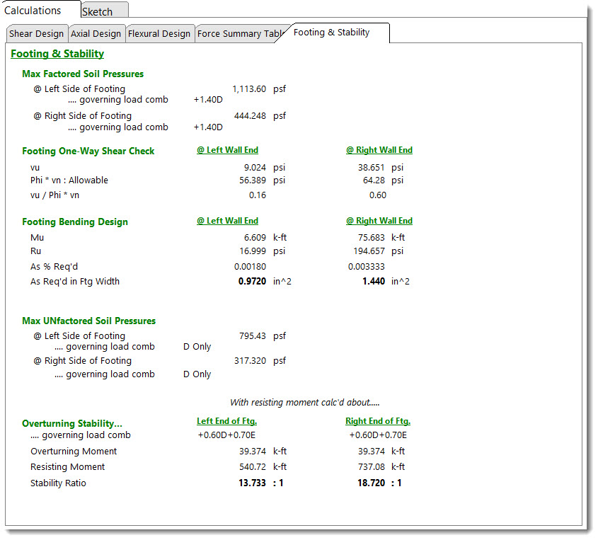
Footing Design Combination Pressures: Reports the maximum factored soil pressures at the left and right sides of the footing, along with the load combination responsible for producing each of those pressures. These are used in the reinforced concrete design calculations for the footing.
Footing One-Way Shear Check: Reports the results of the one-way shear calculation for both ends of the footing.
For footings designed per ACI 318-14 and earlier, the nominal shear strength is ϕ * 2 * λ * sqrt(f'c), where ϕ = 0.75.
For footings designed per ACI 318-19, the nominal shear strength is per the one-way shear strength provisions of §22.5 and Table 22.5.5.1 (as referenced by §13.3.6.1 and §7.5.3.1) and ϕ = 0.75. One way shear capacity assumes no transverse footing reinforcement. Therefore, Av is less than Av,min, and equations (a) and (b) from Table 22.5.5.1 need not be considered.
Footing Bending Design: Reports the results of the flexural analysis and design including recommended reinforcing options to satisfy the required area of steel.
Soil Pressure Combination Pressures: Reports the maximum unfactored soil pressures at the left and right sides of the footing, along with the load combination responsible for producing each of those pressures. Unfactored soil pressures are compared to the allowable soil bearing pressure provided by the user.
Overturning Stability: Reports the overturning analysis performed about each end of the footing including the overturning moment, the resisting moment, the stability ratio, and the governing load combination.
 <
<