Seismic Loads |
  
|
Seismic Loads |
|
You can choose to apply seismic force from lateral earth pressure and/or from wall self-weight.
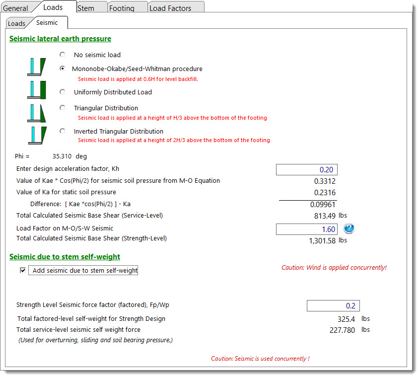
Seismic Lateral Earth Pressure
This category is used to specify whether seismic lateral earth pressure is to be considered or not. If it is to be considered, the program offers the option of two different methods:
•Mononobe-Okabe/Seed-Whitman procedure, or
•Simplified procedure per Geotechnical report
Mononobe-Okabe/Seed-Whitman Procedure
By entering kh the program will calculate KAE and KA using the Mononobe-Okabe/Seed-Whitman equations for a yielding wall (cantilevered).
If it is a non-yielding wall (restrained) the added lateral force per square foot is computed using Fw = kh(density)(retained height), in psf. Common kh values range from 0.05 to 0.30, depending upon area seismicity. Some sources indicate that kh = SDS / 2.5, but jurisdictions and interpretations vary.
Both the static soil pressure component and the added seismic component will be displayed. The resultant seismic component is assumed to act at 0.6 x retained height. The seismic component is assumed to vary from an intensity of X at the bottom of footing to an intensity of 4X at the top of the retained height.
Mononobe-Okabe/Seed-Whitman Methodology
Two excellent references on the subject include Basics of Retaining Wall Design 11th Edition by Hugh Brooks and Seismic Earth Pressures on Deep Building Basements by Lew, et al.
The program computes KAE (coefficient for combined active and earthquake forces) per the Coulomb formula, modified by Mononobe-Okabe/Seed-Whitman, to account for earthquake loading, where the term θ is the angle whose tangent is the horizontal ground acceleration. (Note that if Kh = 0, θ = 0, then KAE = KA.) Vertical acceleration is neglected, resulting in a more conservative KAE.
KAE = active earth pressure coefficient, static+seismic
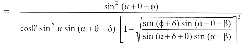
Where θ = tan-1 Kh, α = wall slope to horizontal (90 degrees for a vertical face), ϕ = angle of internal friction, β = backfill slope, and δ = wall friction angle.
For a vertical wall face and δ assumed to be ϕ/2, KAE becomes:
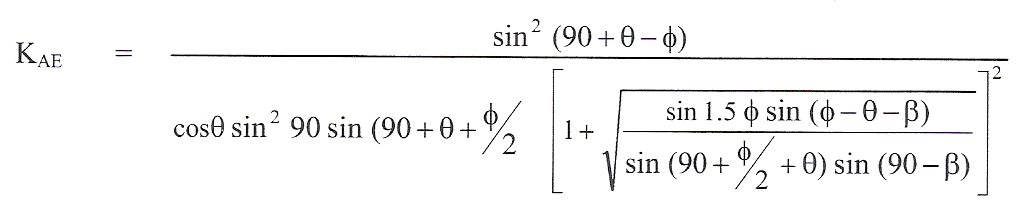
The values KAE and KA are displayed.
For the horizontal component, the forces are multiplied by cos δ (wall/soil interface angle).
Total force (active and seismic) = PAE = 0.5(γ) KAE H2 where γ = soil density and H = retained height.
Since the total force PAE consists of two components, static (PA, as previously computed for static forces) with triangular distribution and the earthquake (PAE - PA) with an inverted semi-triangular distribution with an assumed point of application at 0.60 x height, the combined (static and EQ) point of application is determined by
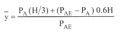
which is displayed as "Ht. to static + EQ point of appl."
Total base shear for both static force and added seismic force are displayed.
From Seismic Earth Pressures on Deep Building Basements by Lew, et al:
If the Mononobe-Okabe analysis is used to determine the lateral seismic earth pressure, the lateral earth pressure should consist of the static active earth pressure and the seismic increment of earth pressure as discussed in the previous section. Presumably, the load factor of 1.6 in Eq. (8) would be applicable to the total earth pressure in this case. However, as noted above, a reduced load factor would be appropriate when considering the transitory nature of the seismic component and the low likelihood of the load maxima occurring simultaneously. Accordingly a lower load factor of 1.0 is proposed to be applied to the seismic increment component of earth pressure while the 1.6 load factor is applied to the static active pressure component. To facilitate such loading combination the geotechnical engineers would have to separate earth pressure components attributable to the active earth pressure condition and the seismic increment of earth pressure when using the M-O method.
Simplified procedure per Geotechnical report
Use this method if a geotechnical report specifies added seismic load as a factor multiplied by the retained height, such as X*H, where X is the multiplier and H is the retained height, enter that multiplier here. Using this method, the seismic lateral force will be applied uniformly over the retained height. Since this is a factored force it will be reduced by 0.7 for use in sliding, overturning, and soil bearing calculations.
Seismic due to stem Self-Weight
If you indicate that you want the program to consider the seismic effect due to the self-weight of the stem, then you will specify a value for the factor Fp/Wp, which will be used to calculate a uniform seismic force in psf (kh x (wall weight). If the wall has multiple stem sections, each will be calculated separately and accumulated for the base shear and moment.
NOTE: The kh values entered are the design accelerations (not necessarily peak ground acceleration as may be given in a geotechnical report) and must be determined per procedures in the applicable code. The program then applies the appropriate Load Factors (1.0 for concrete design and 0.7 for serviceability checks).
 <
<