This data table controls how all of the loads are combined, and also enables you to have member self weight loads automatically considered in specified directions. Note that there is are three Load Combination tabs:
•ASD Load Combinations or LRFD Load Combinations (Based on your selection of Design Method on the General tab. Used for member design code checks.)
•Reaction Combinations (Always service level combinations. Used to calculate reactions.)
•Deflection Combinations (Always service level combinations. Used to calculate deflections.)
Load Combination Set
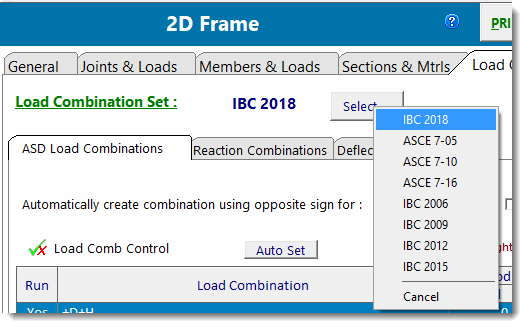
The Select button is used to retrieve load combination sets from the built-in load combination database and place them in the list. Clicking it will display a dropdown menu listing the load combination sets currently included in the database.

Add (plus button)
This button adds a load combination line to the list. You can then edit the factors.
Delete (minus button)
This button deletes the currently selected load combination from the list.

This button allow you to edit the currently selected load combination.
Description of columns in table
Run
This column is a Yes/No toggle to control whether that load combination is used or ignored.
![]()
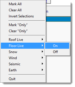
This button allows you to change the Run setting for all the load combinations at once using several options.

Load Combination
This is column represents the load combination. It consists of abbreviations for each included load type along with the associated numeric values that represent the respective load factors. You cannot directly edit this string. It is constructed automatically based on the entries you make in the following columns.
Note in the following image how the Load Combination Name is constructed from the specified values:

Load Duration Factor (Not a load factor. Applies to wood designs only.)
This value acts as a multiplier on the allowable stress for the corresponding load combination.
Individual Load Factors
Enter the numeric value to be applied to each type of load.
0.2*SDS*Seismic Factor
When a value of Sds is specified, this column will report the additional component of vertical load that is to be included due to seismic loading.
Member Self Weight
The controls at the bottom of the Load Combinations tabs indicate whether the program should automatically apply member self weight. Note that automatic application of self-weight can be set up differently on the three Load Combination sub-tabs, if desired. Alternatively, there is a convenience button to copy the self-weight settings from the first tab to the other two tabs, if the goal is to make them all the same.
When self-weight is non-zero, the module will calculate the weight of each member (as cross sectional area * density * length) and consider that weight during the analysis.
Note that the controls allow for the self-weight to be assigned to the Dead Load or the Seismic Load case, and to be assigned a direction and a percentage if desired. This makes it possible to model, say, 30% of the self-weight as an applied lateral load to be considered a Seismic Load.
