General Footing |
  
|
General Footing |
|
This module provides analysis of a rectangular footing with applied axial load, overburden, moment and shear loads.
The module allows you to move the axial load application position off-center of the footing, and provides automatic calculation of allowable soil bearing pressure increases based on footing dimensions and/or depth below surface.
The module checks service load soil pressure, overturning stability, sliding stability, flexure at each of the four pedestal faces, 1-way shear at 'd' from each of the four pedestal faces, and punching shear along a perimeter located 'd/2' from the pedestal faces.
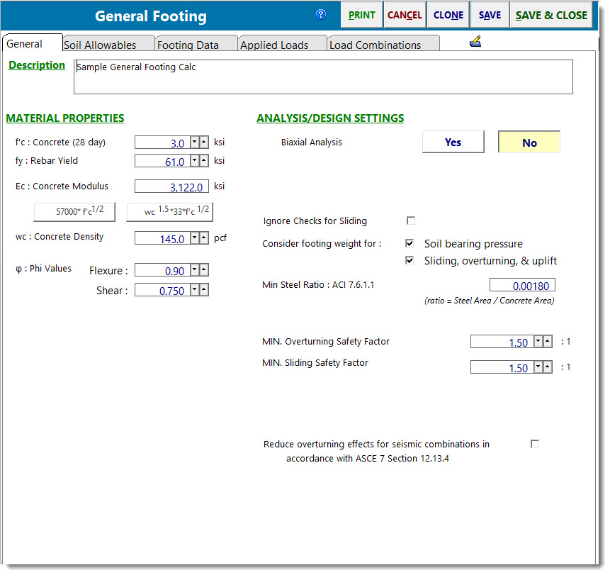
General
Click to Calculate (Button is only visible when biaxial analysis is selected)
Due to the iterative nature of the calculations that are required for a biaxial analysis, it would be undesirable to rerun the entire analysis and design every time an input parameter changes. So for reasons of efficiency, the program automatically goes into manual recalculation mode when biaxial analysis is selected. Click this button any time you wish to recalculate with the current input parameters.
f'c
28-day compressive strength of the concrete.
fy
Yield point stress of reinforcing.
Ec
Modulus of elasticity of concrete.
Concrete Density
The density of the concrete is used to calculate the self-weight of the pedestal and footing when that option is selected. Note that code modifications for lightweight concrete are not applied in this module. The purpose of this input is mainly to allow the user to specify something in the range of 145 to 150 pcf.
Phi Values
Enter the capacity reduction values to be applied to Vn and Mn.
Biaxial Analysis
Select Yes or No to indicate if a biaxial analysis is to be performed. If a biaxial analysis is performed, the solution will consider moments applied simultaneously about the two orthogonal axes of the footing. If a biaxial analysis is NOT performed, the solution will consider moments applied about the two orthogonal axes to be acting non-concurrently.
Amount of Edge Length for M & V (Only displayed when biaxial analysis is selected)
When calculating shear and moment for footings where the maximum soil pressure values occur at the corners, this value specifies the fraction (as a decimal) of the footing dimension from the edge to use when calculating moments and shears due to variable soil pressure in that region. A smaller value for this variable will produce a more conservative design, because it will focus on a narrower strip which is experiencing the highest soil bearing pressure.
Ignore Checks for Sliding
Select this option if sliding is not a design consideration for any particular reason.
Consider footing weight when determining soil bearing pressure
Select this option to have the module calculate the self-weight of the footing and apply it as a downward load when determining soil bearing pressures. The self-weight will be multiplied by the dead load factor in each of the Soil Bearing Pressure load combinations.
Note: This option should generally be selected. Deselecting this option can lead to incorrect soil bearing pressure calculations in footings with moment. If the goal is to try to compare soil bearing pressures to net allowable pressures, then it would be advisable to use the option on the Soil Allowables tab to "Increase Bearing by Footing Weight" or adjust the allowable bearing pressure manually if the design parameters warrant further adjustment.
Consider footing weight when determining sliding, overturning and uplift
Select this option to have the module calculate the self-weight of the footing and apply it as a downward load when determining sliding, overturning and uplift factors of safety. The self-weight will be multiplied by the dead load factor in each of the Stability load combinations.
Min Steel Ratio - Temperature/Shrinkage
Enter the minimum ratio for temperature/shrinkage steel, calculated using the full footing thickness. This will trigger a warning message if the section is under-reinforced.
Note: This check is performed assuming that only one mat of the defined rebar will be provided. If the design has net uplift, such that a top mat is warranted, or if a top mat will be provided anyway, then be aware that the program will still only consider the contribution of one mat toward meeting the Temperature & Shrinkage requirement. In this case, it may be more convenient to set the T&S ratio to a value that represents one-half of the total, knowing that the two mats will be sufficient to provide the full amount required.
Minimum overturning safety factor
Enter the minimum allowable ratio of resisting moment to overturning moment. If the actual ratio is less than the specified minimum ratio, it will trigger a message that overturning stability is not satisfied.
Minimum sliding safety factor
Enter the minimum allowable ratio of resisting force to sliding force. If the actual ratio is less than the specified minimum ratio, it will trigger a message that sliding stability is not satisfied.
Consider ACI 10.5.1 & 10.5.3 as minimum reinforcing
Select this checkbox if you wish to have the module consider ACI 318 Sections 10.5.1 and 10.5.3 in the determination of minimum reinforcing.
Soil Allowable Values
Allowable Soil Bearing
Enter the allowable soil bearing pressure that the soil can resist. This is a service load resistance and will be compared to calculated service load soil pressures (loads not factored as in strength design).
Soil density
Enter the density of the soil in pcf.
Footing base depth below soil surface
The distance from the bottom of the footing to the top of the soil. This value is used to determine allowable soil bearing pressure increases and soil passive sliding resistance, but it is not used in any other calculations in this module.
Increase bearing by footing weight
Click [Yes] to tell the module to calculate the weight of one square foot (plan view) of footing weight and add it to the allowable soil bearing value. This has the effect of not penalizing the soil for the self weight of the footing, and is useful for situations where the geotechnical engineering report provides allowable net bearing pressures.
Soil passive sliding resistance
Enter the value of passive soil pressure resistance to sliding. This value will be used to determine a component of sliding resistance that is generated by the passive pressure of the soil. The sliding resistance due to passive pressure is then added to the sliding resistance due to friction to determine the total resistance to sliding for each load combination.
Coefficient of Soil/Concrete Friction
Enter the coefficient of friction between soil and footing to use in sliding resistance calculations.
Soil Bearing Increase
This section allows you to specify some dimensions that, when exceeded, will automatically increase the allowable soil bearing pressure.
Increases based on footing depth: Provides a method to automatically apply increases to the basic allowable soil bearing pressure based on footing depth below some reference depth. Collects the following parameters:
Allowable pressure increase per foot: Specifies the amount that the basic allowable soil bearing pressure can be increased for each foot of depth below some reference depth.
When base of footing is below: Specifies the required depth in order to start realizing incremental increases in the allowable soil bearing pressure on the basis of footing depth.
Example: Assume the following: Basic Allowable Soil Bearing Pressure = 3 ksf. Footing base is 6'-0" below soil surface. The Geotechnical report specifies that a 0.15 ksf increase in bearing pressure is allowed for each foot of depth when the base is deeper than 4' below top of soil. Since you've indicated that the footing is 6' below the soil surface, the module will automatically calculate the adjusted allowable soil bearing pressure to be 3 ksf + (6' - 4') * 0.15 ksf = 3.30 ksf.
Increases based on footing plan dimension: Provides a method to automatically apply increases to the basic allowable soil bearing pressure based on footing dimensions greater than some reference dimension. Collects the following parameters:
Allowable pressure increase per foot: Specifies the amount that the basic allowable soil bearing pressure can be increased for each foot of length or width greater than some reference dimension.
When maximum length or width is greater than: Specifies the required dimension in order to start realizing incremental increases in the allowable soil bearing pressure on the basis of footing dimension.
Example: Assume the following: Basic Allowable Soil Bearing Pressure = 3 ksf. Footing measures 12'-0" x 6'-0". The geotechnical report specifies that a 0.15 ksf increase in soil bearing pressure is allowed for each foot when the largest plan dimension of the footing is greater than 4'. The module will automatically calculate the adjusted allowable soil bearing pressure to be 3 ksf + (12' - 4') * 0.15 ksf = 4.2 ksf.
Note: Increases based on footing depth and plan dimensions are cumulative.
Maximum Allowed Bearing Pressure: Allows the specification of an upper limit on the soil bearing pressure that cannot be exceeded, regardless of the above increases.
Adjusted Soil Bearing Pressure: Reports the allowable soil bearing pressure adjusted for footing weight and depth and dimensions as specified.
Footing Data
This tab is where you enter the footing and pedestal dimensions.
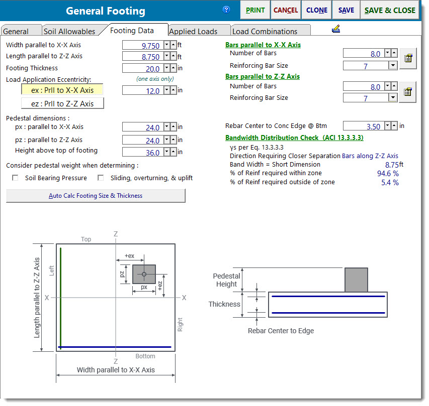
Width, Length & Thickness: defines the overall dimensions of the footing.
Load Location: defines the offset from the center of the footing where the axial load is applied. If a biaxial analysis is NOT being used, then only one direction can be used.
Pedestal dimensions: If a concrete pedestal bears on the footing, its dimensions can be specified here. The px and pz dimensions are used to define the locations on all four sides where one-way shear, two-way shear and bending moment are calculated. If you enter a nonzero height, then you can choose to have the weight of that prism calculated and added as dead load. Any applied overburden loads will be omitted from the area defined as the pedestal dimension along the xx and yy axis, regardless of the specified height of the prism.
Note: If no pedestal is defined, then the load location will be treated as the face of the pedestal when determining the critical locations to check shear and flexure.
Rebar Definitions: Specify the number and size of rebar parallel to each axis.
Rebar Location: Specify the distance from the center of the rebar to the bottom surface of the footing. Note that this is the dimension to the center of the rebar, not the clear cover.
Note: Bars are assumed to be fully developed at the locations where they are required. It is the engineer's responsibility to validate that assumption. The program is not taking rebar development length into consideration.
Consider Pedestal Weight When Determining: This option allows the user to specify whether or not the self-weight of the pedestal is to be considered when determining the soil bearing pressure, and separately, whether or not the self-weight of the pedestal is to be considered when performing the checks for sliding, overturning, and uplift.
Applied Loads
This tab allows you to specify the axial load, shear, and moment applied to the pedestal, as well as an overburden load applied to the entire plan dimension of the footing (except the area designated as the pedestal).
Enter vertical loads with a positive sign for downward direction. Shear loads are applied at the location of the pedestal. If the pedestal is specified to have a height, the shear will be applied at that height and will create a moment on the footing equal to Shear Load * (Footing Thickness + Pedestal Height).
Note! This module will not allow a net uplift on the footing. If the result of the factored axial loads (dead, live, wind, etc) produces a negative load sign, the module will not recalculate and will notify you of which load combination resulted in net uplift.
Load Combinations
The Load Combination tab offers three subtabs: LRFD Load Combinations, Soil Pressure Combinations, and Stability Combinations. They are all based on the selected Load Combination Set.
The LRFD load combinations are used to calculate moments and shears in the footing for use in determining stresses and required reinforcing. The combinations on this tab are at the strength-level.
The combinations on the other two tabs are at the service-level, and are used for checking soil bearing pressure and stability, respectively.
Note: The General Footing module is applying the factored loads to the footing and determining a different eccentricity than was determined using the service loads for the soil bearing pressure check.
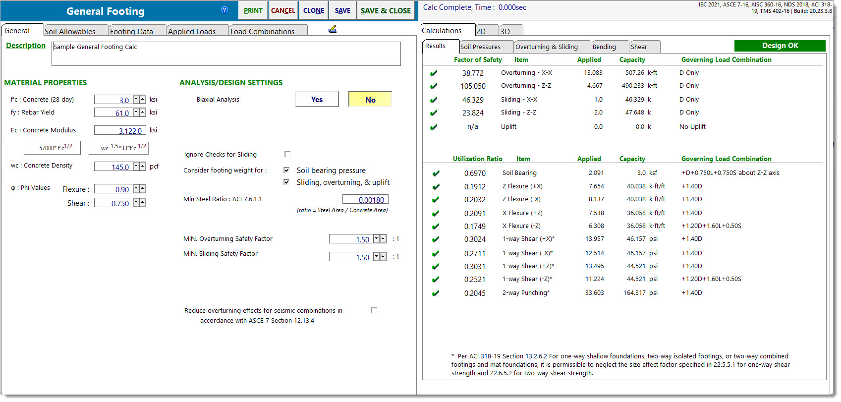
Results
This tab provides a summary of all calculated values. The stress ratios, applied & allowable values and load combination for those governing values are reported.
Soil Pressures
This tab summarizes the calculated service load soil bearing pressure for moments & shears applied about the specified axis, for each load combination.
Overturning & Sliding Stability
This tab provides the calculations for overturning and resisting moment of the footing about each axis for each load combination, and sliding and resisting forces in each direction for each load combination.
Note that the program is set up to look for overturning and resisting forces individually. For example, take the situation where the footing is subjected to equal and opposite shears at a given elevation. Common sense dictates that these forces cancel each other, and the footing experiences no net applied overturning moment from them. But the program treats one of the two equal and opposite forces as an overturning force, and the other as a resisting force. So for these two forces, there IS a net overturning moment reported, but the resisting moment ALSO considers the effect of the opposing load, so the accounting used to determine the overturning ratio is proper.
Footing Bending
This tab provides a summary of the calculated factored load moment at all four edges of the pedestal perimeter for each load combination. It indicates whether the named load combination produces tension on the top surface of the footing or the bottom.
Note: In cases where tension occurs on the top of the footing, the flexural check will be based on the assumption that the defined rebar mat is provided on the top surface of the footing. The user must review the results and determine if any load combinations actually require a top mat of reinforcing, or if the footing could be reinforced with a bottom mat only.
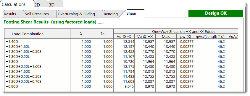
Footing Shear
This tab provides a summary of the calculated factored load shear at all four edges of the pedestal perimeter for each load combination. Two-way or punching shear is also calculated.
2D Sketch
Diagram
3D Rendering
 <
<