Key Design & Sliding Options |
  
|
Key Design & Sliding Options |
|
This screen is used to indicate whether a key is to be used, and if so, specify its dimensions. This screen also collects information about the design intent for the sliding check, and presents a summary of the sliding forces.
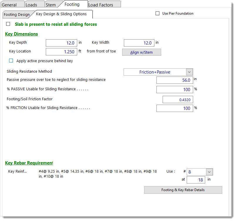
Slab is present to resist all sliding forces: Provides a way to communicate to the program that sliding is not a design consideration, because in the designer's judgment, sliding is completely precluded, such as by a slab on grade on the toe side of the wall that prevents sliding altogether. If this option is selected, the lateral sliding force is displayed for checking the resistance offered by the slab, and the slab is assumed to be at the top of the footing, but not higher.
Key Dimensions
| Key Depth: | Depth of the key below the bottom of footing. The bottom of the key is used as the lower horizontal plane for determining the size of the passive pressure block from the soil in front of the footing. Adjust this depth so the sliding safety factor is acceptable, but not less than 1.5. |
| Key Width: | Width of the key, measured along the same direction as the footing width. This is usually 12"-14", but generally not less than one-half the key depth so flexural stresses in the key are usually minimal. |
| Key Location: | Enter the distance from the front edge of the toe to the front of the key. Do not enter a distance greater than the footing width minus key width. |
| Align with Stem: | Click this button to align the front edge of key with the front of the stem. If the key width is then set to a value that is reasonably close to the stem width, the stem bars may be able to be extended down into the key to facilitate rebar development. |
| Apply active pressure behind key: | When this option is selected, the program will consider the driving force to extend all the way to the bottom of the key. If this option is NOT selected, then the driving force will not extend below the bottom of the footing. |
Note: IBC 2015 was worded in such a way as to confuse this issue and imply that it was a requirement that active pressure must extend to the bottom of any key. The actual intent was expanded upon in subsequent documents to clarify that the intent was to require active pressure to extend to the bottom of a key in situations where it could be reasonably anticipated that the soil on the low side of the wall (providing passive resistance) might be removed during the service life of the wall, such as in a scour condition. This verbiage was revised in IBC 2018 to remove the ambiguity.
| Sliding Resistance Method: | Enter whether sliding resistance will be by friction and passive pressure or by cohesion and passive pressure. |
| Soil Over Toe to Neglect for Sliding Resistance: | Since the soil over the toe of the footing may be loose and uncompacted, it may have little or no passive resistance. This entry gives the option to neglect some portion of the Height of Soil Over Toe entered in the General tab. You can neglect the soil over toe plus the footing thickness, if desired. |
| % Passive Usable for Sliding Resistance: | Enter a value from zero to 100% to indicate the percentage of the calculated passive pressure that will be used as resistance in the sliding calculation. This may be a stated restriction in the geotechnical report. |
| Footing/Soil Friction Factor: | Enter the friction factor here. It usually varies from 0.25 to 0.45, and is generally provided by the geotechnical engineer. |
| % Friction Usable for Sliding Resistance: | Enter a value from zero to 100% to indicate the percentage of the calculated friction force that will be used as resistance in the sliding calculation. This may be a stated restriction in the geotechnical report. |
Summary of Sliding Forces
| Lateral Force @ Base of Footing: | This is the total lateral force against the stem and footing which causes the wall to slide and which must be resisted. |
| Less Passive Pressure Force: | This uses the allowable passive pressure in pcf and the available depth ("footing thickness" plus "soil above toe" less "height to neglect") multiplied by the "percent usable" you specified to compute the total passive resistance. Weight due to toe surcharge, if applicable, will also be incorporated into the calculation of the passive force. If a key is used, the available passive pressure depth will be to the bottom of the key. |
| Less Friction Force: | This is the total vertical reaction multiplied by the friction factor, and then multiplied by the "percent usable" you specified. |
| Added Resisting Force Required: | If this value is indicated as 0.0 lbs., then there is no requirement for additional resisting force in order to achieve a static balance of forces, but it does not necessarily mean that there is an adequate factor of safety against sliding. Watch the Sliding Ratio on the Results tab, Summary sub-tab for an adequate value (usually 1.5). Consider adding a key or modifying footing geometry if required. |
Added Resisting Force Required for 1.5:1 Factor of Safety:
This is the additional resisting force that would be required in order to achieve a 1.5 safety factor. If this value is indicated as 0.0 lbs., then the Siding Ratio is already 1.5 or greater.
Key Rebar Requirement
| Key Reinforcing: | This area indicates the permissible spacing values for a variety of logical rebar sizes, and allows the user to specify the size and spacing of the rebar in the key. |
Sliding Factor of Safety: This reports the ratio of passive and friction resistance to the total lateral force. This should be at least 1.5, or 1.1 if seismic is activated.
NOTE: If lateral restraint is provided by an abutting floor slab (by checking the "Slab is present..." box), the sliding factor of safety will not be displayed, but the “Lateral Force @ Base of Footing” will be displayed for checking restraint adequacy of the slab.
 <
<