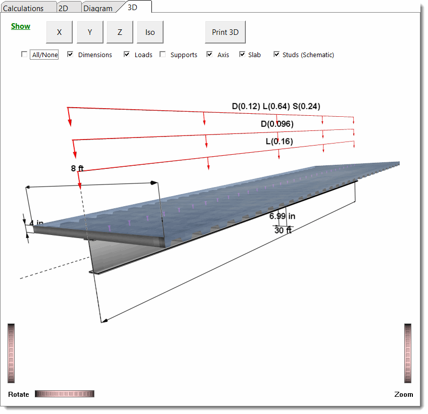
This module provides analysis and design of AISC steel sections acting compositely with a concrete slab that is continuously connected to the compression flange of the beam with suitable shear connectors.
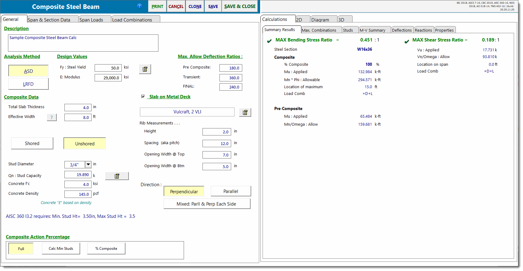
Features of the module include:
•The concrete slab can be either full depth or cast over formed steel decking, with rib orientation perpendicular or parallel to the beam.
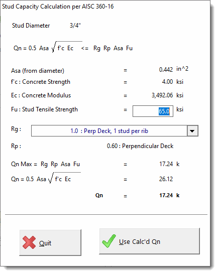
•Stud capacity can be calculated by the module using standard AISC procedure.
•Normal or lightweight concrete may be used for both strength and deflection calculations.
•Both shored and unshored construction techniques can be analyzed by the module.
•ASD or LRFD design methods can be chosen.
•Flexible specification of shear studs is available.
•Very flexible loading specification, including the ability to specify construction loads (applied to pre-composite checks only), loads that apply to both the pre-composite and post-composite checks (always applied), and loads that are only applicable to the post-composite checks (applied after curing).
•Extensive load combination capability.
•Can use many sections from the AISC databases.
General
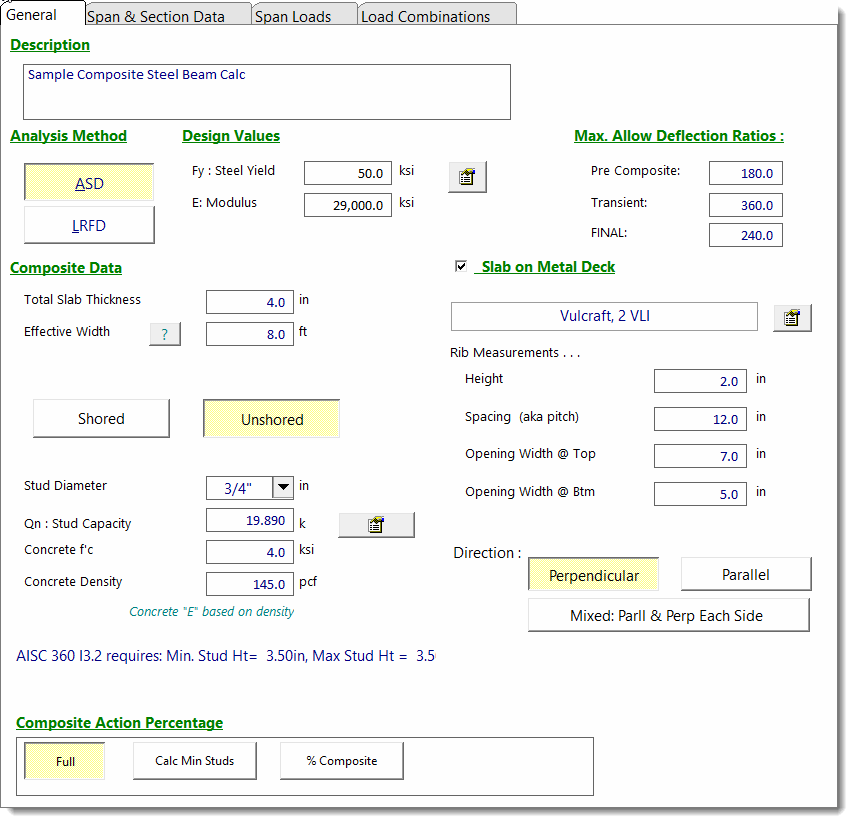
This tab gathers all input except for the beam section size and loads.
The Analysis Method category offers an option of ASD or LRFD methods.
The Composite Data category offers all of the necessary input fields to completely specify the slab, its effective width, stud information and metal deck specification (if applicable).
For Qn you can enter the value directly or click the ![]() button to display the stud capacity calculation dialog:
button to display the stud capacity calculation dialog:
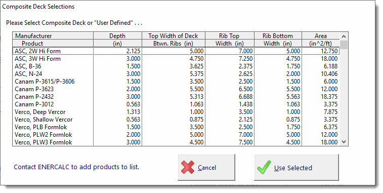
When you click the checkbox for Slab on Metal Deck, the associated input fields appear to allow the selection of a manufactured deck product, or the manual specification of the required deck properties.
Click the ![]() button to display the metal deck selection window as shown below, or simply enter the deck cross section data in the dimension input fields:
button to display the metal deck selection window as shown below, or simply enter the deck cross section data in the dimension input fields:
Partial Composite Action
This category provides three ways to have the module calculate stud requirements.
Full Composite tells the module to use the number of studs necessary to provide full Vh shear resistance for the slab to beam connection.
Specify % Composite allows the user to enter a percentage of maximum composite action. The module will then determine the number of studs needed for that Vh' and complete the bending capacity calculations.
Calc Min Studs tells the module to calculate the minimum number of studs (greater than 25% composite per code recommendations) that will adequately supply the required moment capacity based on the applied moment.
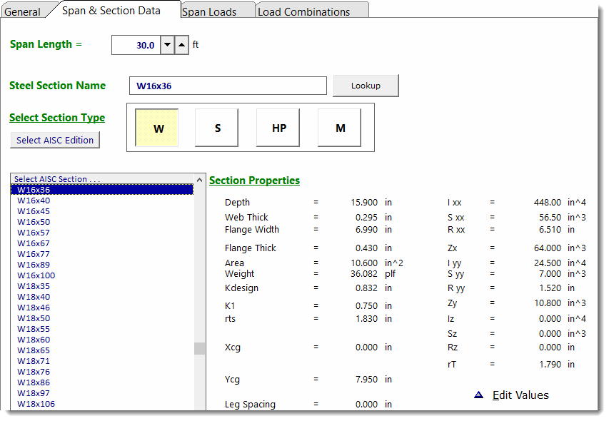
Span & Section Data
This is basically the same tab used for a normal steel beam except that there is no ability to specify unbraced compression flange lengths. For regions of positive moment, the top flange is considered to be continuously braced by its composite connection to the concrete slab.
Note: Use caution in situations where the applied loading may result in regions of negative moment, because this module considers the bottom flange to be continuously braced.
Span Loads
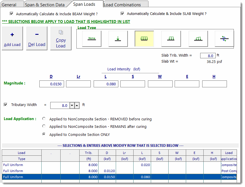
This tab is basically the same as the normal load entry for other beam design modules except for two differences:
1 - There are two checkboxes that allow the user to indicate whether the module should automatically calculate and apply the beam self weight and slab self weight.
2 - There are three "Load Application" options that allow the user to specify the sequencing of the specified loads as follows:
•Non-Composite Section - Removed before curing: Dead Load and/or Live Load that will be considered in the pre-composite checks, but not in the post-composite checks.
| Use this load application type to specify temporary Construction Live Load or Construction Dead Load that will be removed before the concrete cures. Do NOT use this load application type to specify permanent loads like the weight of the concrete fill on the metal deck. That type of load should be specified using the next option. |
•Applied to Non-Composite Section - Remains after curing: Dead Load that will be considered in the pre-composite AND the post-composite checks.
| Use this option for loads that will be in place while the section is non-composite and will REMAIN in place after composite action is achieved. Examples might include the weight of the concrete fill on the metal deck or the self-weight of the steel beam. |
•Applied to Composite Section Only: Any type of load that will be superimposed on the cured composite section. These will only be considered in the post-composite checks.
| Use this option for loads that will be placed on the structure only after composite action has developed. Some examples might include the weight of architectural floor finishes and occupancy live load. |
Load Combinations
The function of the Load Combinations tab in the Composite Steel Beam module is the same as in other beam modules.
Results Tabs: This set of tabs provides detailed results for the current calculation. The tabs in the upper right-hand corner of the screen allow the user to select the four major areas available for review: Calculations, 2D Sketch, Diagram, and 3D Rendering.
The Calculations tab offers the following results options:
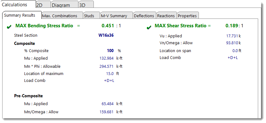
Summary Results tab presents the maximum/governing ratio values from all of the results presented on the Max. Combinations tab. The module looks for the maximum bending stress ratio and presents the components that are calculated to create that ratio.
For the bending stress item the module reports the Pre-Composite bending ratio, which considers all loads specified to be applied to the beam before curing. The resulting moment is compared to the capacity of the steel section acting alone (non-compositely).
For the item reported as Composite, the module considers all loads specified to be applied to the composite section. That moment is then compared to the full composite section moment capacity for the percentage of shear connection specified.
The results indicate the load combination that creates the governing values along with the span id and location at which the governing ratio was found to occur.
The module calculates the maximum total deflection as the sum of the deflection of the non-composite steel section resisting all of the loads that are specified as Pre & Post Composite (always applied) plus the deflection of the composite section resisting all of the loads that are specified as Post Composite Only (applied after curing).
Note! The screen shown below, which gives information for Construction loads, is only for unshored beams. For shored beams the Construction portion of moments is not applicable, so it is not shown.
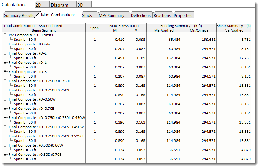
Max Combinations tab presents in more concise detail the bending and shear values for all load combinations.
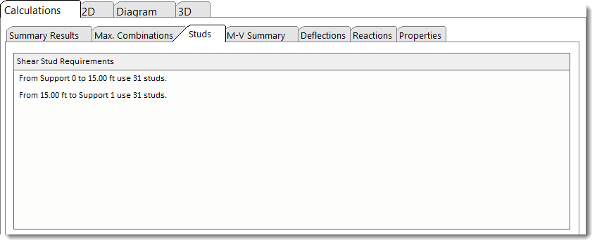
Studs tab presents the shear connector requirements for all span sections. When point loads are present, this chart may list more detailed spacing requirements because of the shear change between applied point loads.
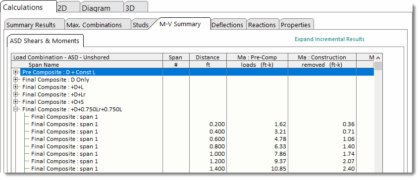
M-V Summary presents shear and moment results. This screen will take on four slightly different forms depending upon the selection of Analysis Method (ASD or LRFD) and shoring (shored or unshored). The example shown below is for an ASD unshored design.
Deflections tab has two versions, one for shored and one for unshored construction. The only differences are the load combinations and the explanations of load applications listed. The unshored version is shown below.
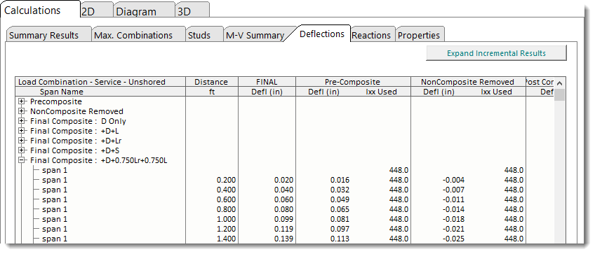
In the Unshored Service Deflections table, the columns warrant some detailed explanation:
The column labeled "Pre-Composite" shows the deflection of the bare steel beam subjected to all loads that are specified to act on the bare steel beam. This would include all loads defined using the "Non-Composite - Removed before curing" option and all loads defined using the "Non-Composite - Remains after curing" option on the Span Loads tab.
The column labeled "Non-Composite Removed" shows the deflection of the bare steel beam due all loads defined using the "Non-Composite - Removed before curing" option on the Span Loads tab. Since these loads are removed before the beam reaches its service condition, these construction load deflections are removed from the total deflection, so that the Total deflection represents a correct net total deflection in the service condition.
The column labeled "Added Post Composite" shows the deflection of the composite section due to the loads that are superimposed on the section after it has achieved composite action. This would include all loads defined using the "Applied to Composite Section Only" option on the Span Loads tab.
The column labeled "Final" is calculated by adding the value in the "Pre-Composite" column to the value in the "Added Post Composite" column and then netting out the value in the "Non-Composite Removed" column. This way, the "Total" deflection represents the full anticipated in-service deflection considering all permanent loads and properly accounting for their sequence of application.
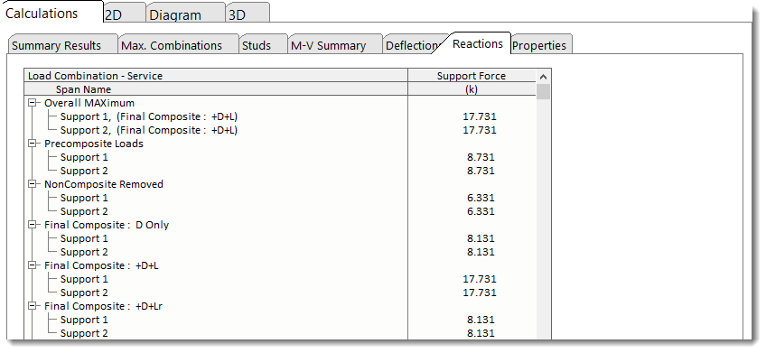
Reactions tab has two versions, one for shored and one for unshored construction. The only differences are the load combinations and the explanations of load applications listed. The unshored version is shown below.
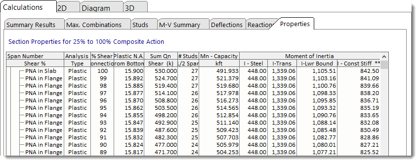
Properties tab shows the calculations for transformed section properties calculated in increments of 1% shear connection, from 100% down to the code minimum 25%. "I Lower Bound" and "I Constant Stiffness" are terms described in AISC 360.
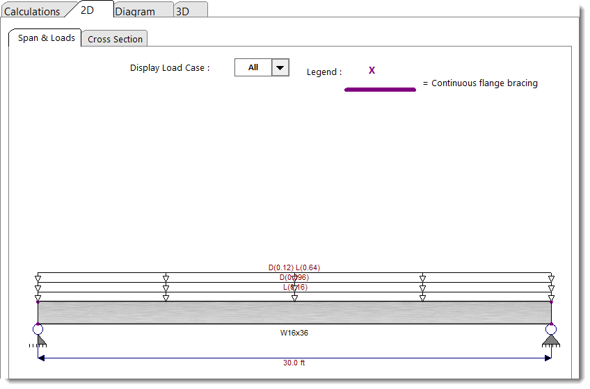
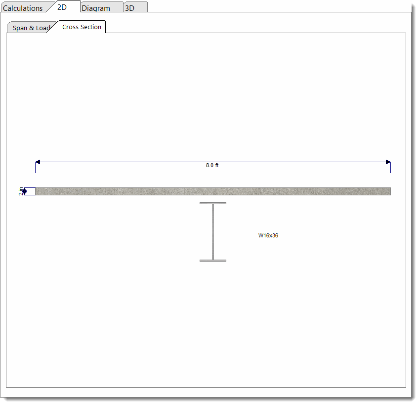
The 2D Sketch tab provides two ways to view a graphic representation of the beam currently being designed:
Span & Loads tab:
Cross Section tab:
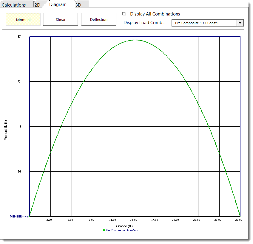
The Diagram tab offers the ability to view shear, moment, and deflection diagrams for selected load combinations:
The 3D Rendering tab displays a 3D view of the beam and offers display options:
