ASCE 7-10/16 Wind Forces, Chapter 27, Part 1 |
  
|
ASCE 7-10/16 Wind Forces, Chapter 27, Part 1 |
|
This module is a presentation of the Wind Forces provisions of Chapter 27, Part 1 of ASCE 7-10 and ASCE 7-16.
Limited documentation is provided here, because all of the references to ASCE 7 are given on the module screens.
General
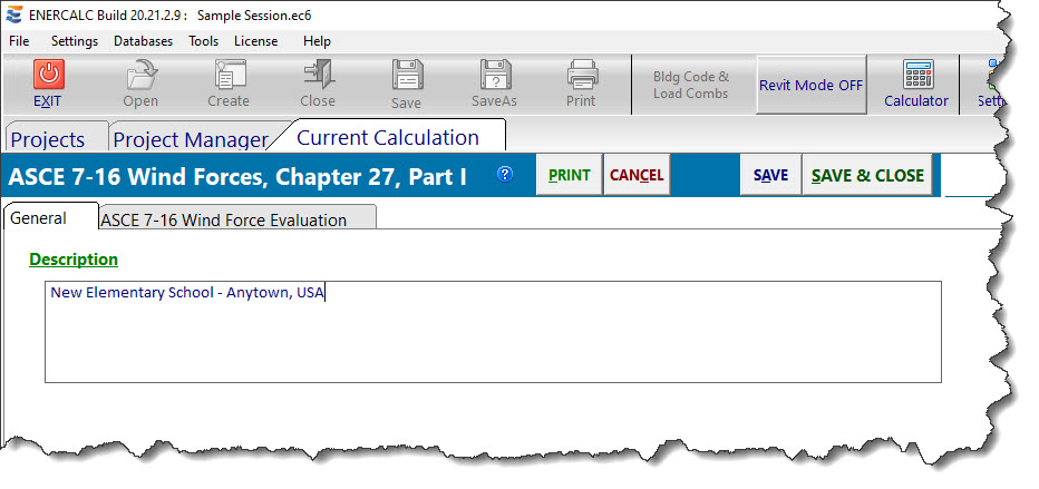
The General tab provides an input field for a general description of the project and/or the wind calculations that are being performed.
ASCE 7-10 / 7-16 Wind Force Evaluation
This tab provides access to a series of Calculation tabs that can be used to store up to ten separate wind calculations. These might be useful for studying different project sites, different architectural concepts, or even evaluating separate buildings in a project.
The Description field can be used to distinguish from among the different wind load calculations that might be defined in a single Project File.
The Print checkbox specifies whether or not the particular wind load calculation will or will not be included when a Print command is clicked or when a Project Print is performed.
General (sub-tab of the ASCE 7-10 / 7-16 Wind Force Evaluation tab)
This tab collects basic data such as Risk Category, Basic Wind Speed, Directionality Factor, Building Dimensions, Exposure Category, Topographic Factor, and information to determine how the building frequency will be determined.
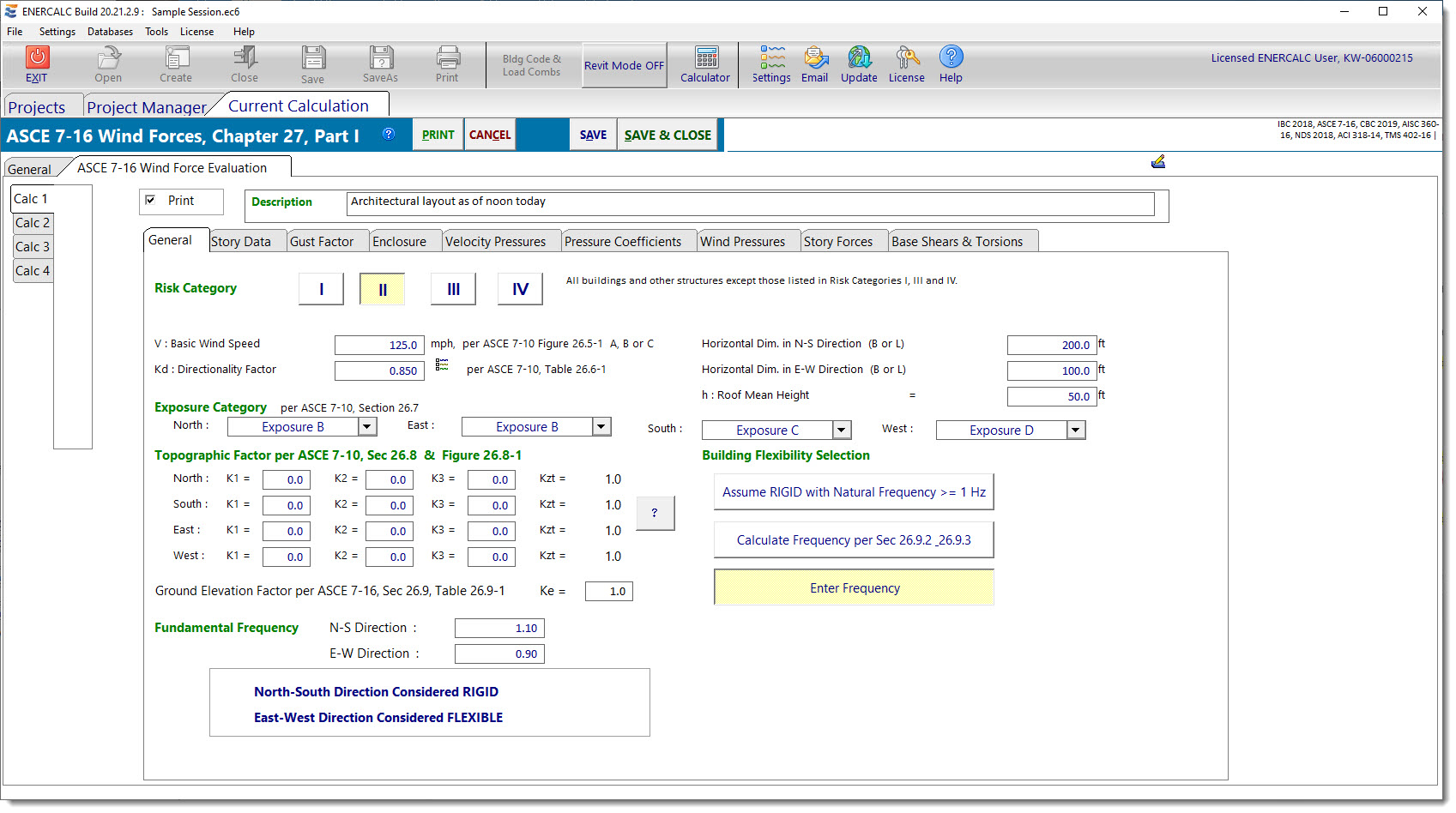
The Risk Category is only for reference in documenting the design. It no longer influences the importance factor, but it does dictate which Wind Speed map to use to determine the Basic Wind Speed.
The Exposure Category is dependent upon the upwind characteristics. Therefore, as different building elevations become the windward face of the structure, it is possible that the Exposure Category will change. For this reason, the program allows the Exposure Category to be defined separately for each building face in turn becoming the windward face.
The Building Flexibility Selection offers three different options for defining the frequency of the building.
•The first option declares that the building will be assumed to be rigid (having a frequency greater than or equal to 1 Hz).
•The second option applies the prescriptive methods in Sections 26.9.2 and 26.9.3 of ASCE 7-10 to approximate the frequency of the building based on construction type/layout and mean roof height.
•The third option allows the user to explicitly specify the frequency in the North-South direction and in the East-West direction.
Note that if the second option is selected, a new tab named "Frequency" will be introduced between the "Story Data" tab and the "Gust Factor" tab.
This tab contains the only difference between ASCE 7-10 and ASCE 7-16, which is the introduction of Ke, the Ground Elevation Factor in ASCE 7-16.
Story Data
This tab collects the data required to define the vertical locations of the stories with respect to finished grade.
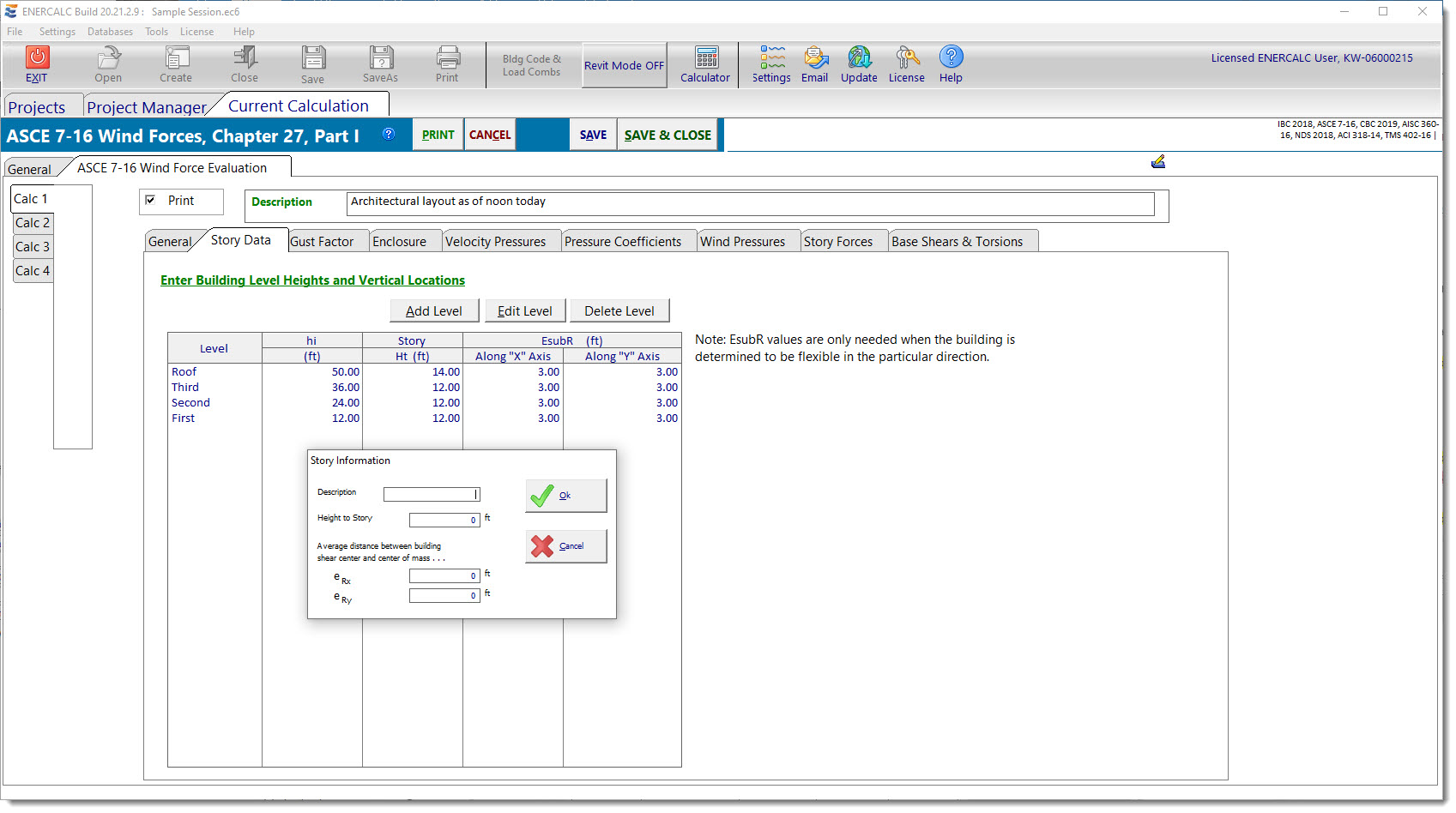
The development of the story data table is controlled by the three buttons: Add Level, Edit Level, and Delete Level, which perform their respective operations on the table of story data.
Clicking Add or Edit opens the Story Information pop-up dialog as shown above. Two items are worthy of note on this dialog. First, the Height to Story is always referenced from grade, so it is looking to collect the height from grade to the story of interest, not the story to story height. Second, the values of eRx and eRy are only used if a building is determined (or defined) to be "Flexible" (< 1 Hz) in a particular direction. So if a building turns out to be "Rigid" in one or both directions, then the values of eRx and eRy are not required in those directions, and the values can be left at zero or a value can be entered, but the program will ignore it.
Frequency (Only displayed if the option is selected on the General tab to "Calculate Frequency")
This tab displays the story data that was previously collected, and it requests the Building Construction Type and the values of Li necessary to complete the check to determine if the approximate methods of frequency determination are applicable.
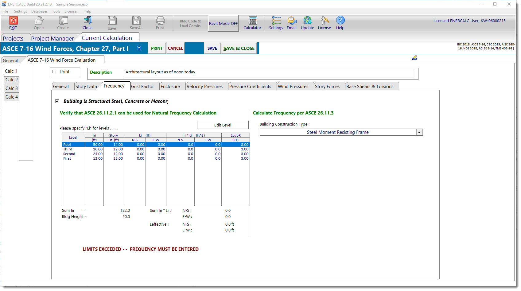
If the approximate methods of frequency determination are found to be applicable, this tab reports the approximate frequency. Otherwise, a message will be displayed to indicate that the approximate methods are not applicable, and that the building frequency must be determined another way.
Gust Factor
This tab displays the results of the Gust Factor determination for each of the four elevations, in turn, being the face of the building that receives positive external pressure.
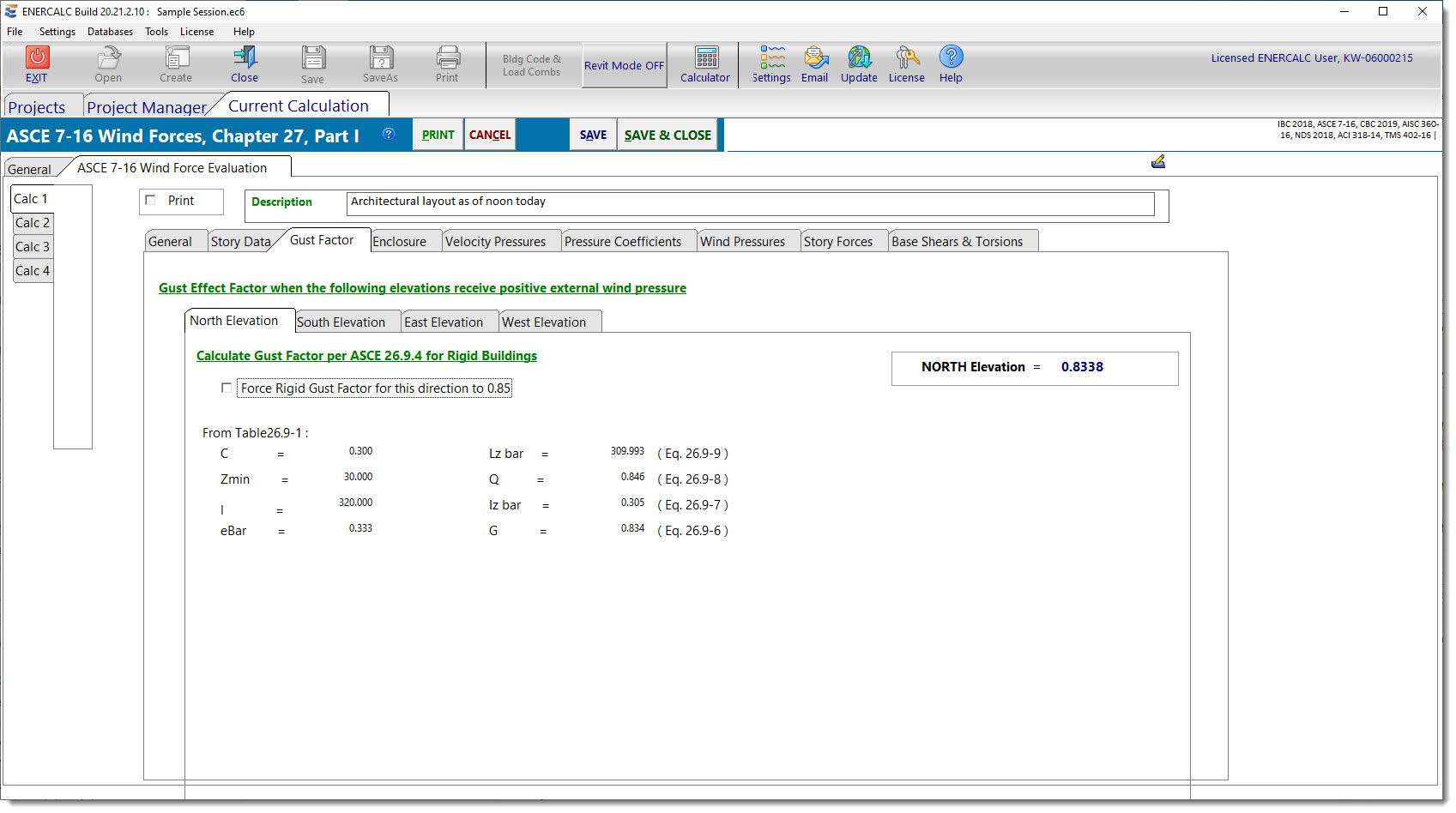
The North, South, East, and West tabs present the calculation and the resulting Gust Factor that will be used in subsequent calculations when the respective building elevation receives positive external pressure.
When the building is categorized as "Rigid" in a particular direction, the program offers the checkbox option to force the value of the Gust Factor to 0.85 when the referenced elevation receives positive external pressure.
When the building is categorized as "Flexible" in a particular direction, the program requires one more value, which is the damping ratio. This value is collected in an input box on the respective direction tab when appropriate, and the value is incorporated into the Gust Factor to be used when the referenced elevation receives positive external pressure.
It is worth noting that many of the parameters used in the calculation of the Gust Factor are dependent upon the Exposure category. Since the Exposure category can vary for each of the four cardinal directions, it is possible that the Gust Factor for use when the North elevation of the building receives positive external pressure may actually be different than the Gust Factor for use when the South elevation of the building receives positive external pressure.
Enclosure
This tab displays the results of the Enclosure determination for each of the four elevations, in turn, being the face of the building that receives positive external pressure.
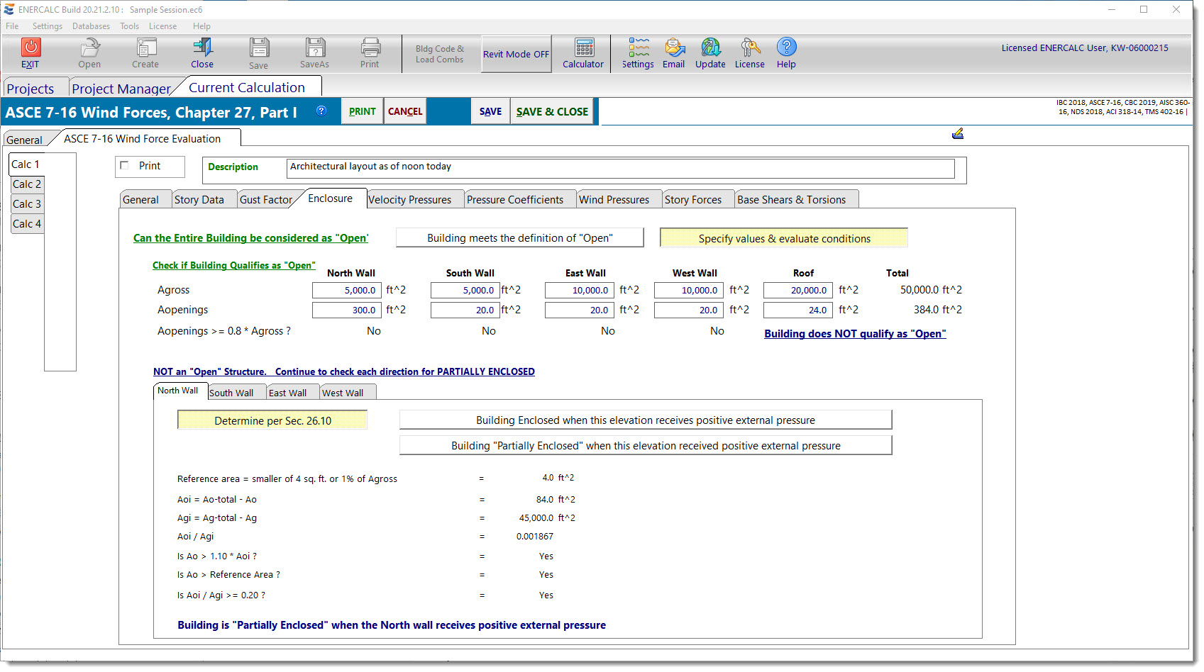
The upper half of this tab is dedicated to evaluating the building to determine whether or not it qualifies as an "Open" structure. The module collects the gross areas of each of the four walls along with the areas of opening in each of the four walls. Based on the data provided by the user, the module performs the calculations and checks the criteria to see if the building qualifies as an "Open" structure. If it does, then the module reports that result. If the building does NOT qualify as an "Open" structure" then additional input fields are displayed to collect the gross area of the Roof, and the area of openings in the roof, and the workflow continues to determine whether the building qualifies as "Enclosed" or "Partially Enclosed". This evaluation takes place four times, considering each of the four walls to be the windward wall, in turn. The intermediate calculations are performed and the results are reported on each of the four wall tabs.
It is worth noting that a building could potentially be considered "Partially Enclosed" when some of its elevations receive positive external pressure, and "Enclosed" when its other elevations receive positive external pressure.
It is also worth noting that convenience buttons have been provided on each of the four wall tabs to allow the user to simply declare the building to be "Enclosed" or "Partially Enclosed" when the selected elevation receives positive external pressure. These have been implemented for situations where the evaluation has already been performed and/or the user is already confident in making a decision by judgment.
The Enclosure classification is used downstream to select appropriate values of GCpi to use when each of the four elevations becomes the windward wall.
Velocity Pressures
This tab displays the results of the Velocity Pressure determination for the various walls when each wall is under leeward, sidewall, and windward wall conditions.
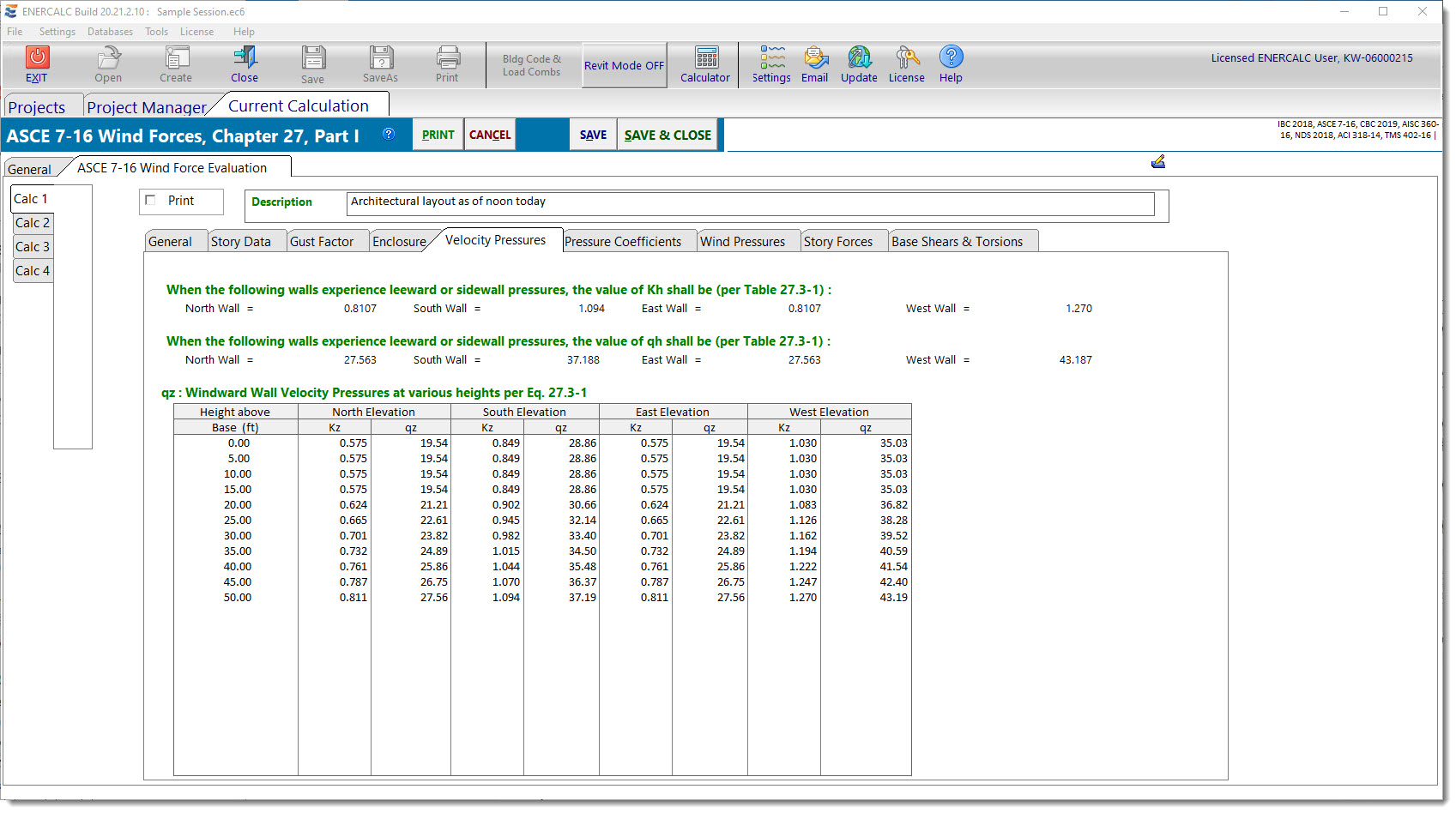
The first row of data reports the values of Kh that are applicable when each of the walls experiences leeward or sidewall pressures.
The second row of data reports the resulting values of qh that are applicable when each of the walls experiences leeward or sidewall pressures.
Next, a table is presented that reports the values of Kz and the resulting values of qz that are applicable, as a function of height, when each of the walls experiences windward wall pressures.
Pressure Coefficients
This tab reports the values of GCpi that are applicable when each of the respective elevations receives positive external pressure. The remainder of this tab is dedicated to collecting the values of Cp or Cn as appropriate for the various surfaces of the building.
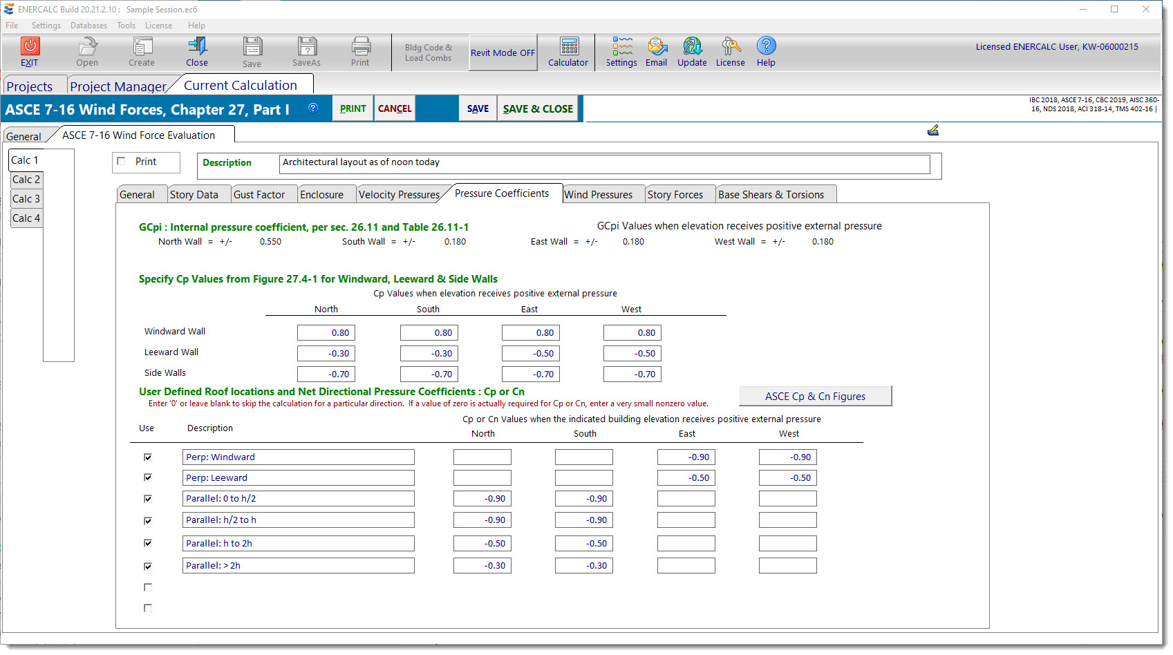
Wall values are collected first, and the input fields collect values of Cp that will be used when each of the four walls is a windward wall, a sidewall, or a leeward wall.
At the bottom of the tab is a customizable table that is set up to receive many lines of Cp or Cn values pertinent to the roof. A convenience button is provided to display the figures that define the Cp or Cn values for various conditions. A glance at the tables reveals that the factors for roofs are frequently dependent upon the wind direction with respect to the ridge, and also dependent upon whether pressures are desired for the windward or leeward surfaces of the roof. So some planning will be required to set this table up to yield the desired results. To make the downstream results most applicable and easy to read, the program has been set up so that a roof pressure value will only be calculated for situations where nonzero values of Cp or Cn have been specified. To put this another way, referring to the table above, there are no values of Cp defined for the North or South elevations for the "Perpendicular: Windward" or "Perpendicular: Leeward" conditions. This is because the ridge is assumed to run in the North-South direction in the hypothetical building being considered. As such, it would not make sense to ask the program to report windward or leeward roof pressures when the wind acts in the north or south directions. So to avoid overpopulating the output with meaningless results, the blank fields will be interpreted by the program as an indication that the corresponding calculation is not required. We will see the benefit of this when we move to the Wind Pressures tab and see how concisely these results are reported.
On a related note, it is worth mentioning that the Cp and Cn tables occasionally report values of zero for certain conditions. These are typically provided for interpolation purposes. But if a situation is ever encountered where a value of zero for Cp or Cn is actually required for design purposes, the user is advised to enter a small nonzero value.
Wind Pressures
This tab reports the values of wind pressures that occur on the various surfaces of the building when the named elevation receives positive external pressure.
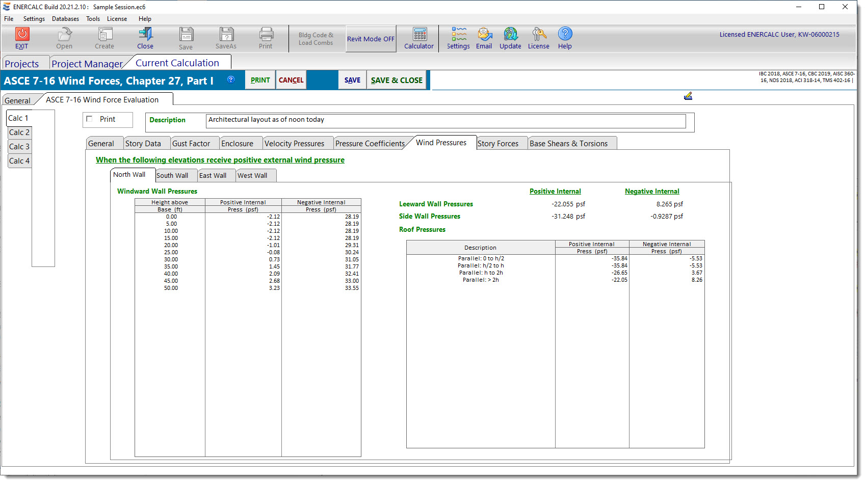
Looking at the screen capture above, we see that the North Wall tab is currently selected. Let's work through this tab thoroughly as an example. As indicated in the on-screen note, we interpret all of the results on this tab as being the pressures that occur on the named surface of the building when the North Wall receives positive external wind pressure. So when we are focused on the North Wall tab:
•The "Windward Wall Pressures" are those that would apply to the North Wall when the North Wall receives positive external pressure.
•The "Leeward Wall Pressures" are those that would apply to the South Wall when the North Wall receives positive external pressure.
•The "Sidewall Pressures" are those that would apply to the East and West Walls when the North Wall receives positive external pressure.
•The "Roof Pressures" are those that would apply to the identified areas measured from the North edge of the roof when the North Wall receives positive external pressure.
Just to drive home the proper interpretation of the values reported on the Wind Pressures tab, let's work through the East tab, so we can interpret some windward and leeward roof pressures. Remember that this hypothetical building is assumed to have a North-South oriented ridge. So when we are focused on the East Wall tab:
•The "Windward Wall Pressures" are those that would apply to the East Wall when the East Wall receives positive external pressure.
•The "Leeward Wall Pressures" are those that would apply to the West Wall when the East Wall receives positive external pressure.
•The "Sidewall Pressures" are those that would apply to the North and South Walls when the East Wall receives positive external pressure.
•The "Perp: Windward Roof Pressures" are those that would apply to the windward (East) portion of the roof when the East Wall receives positive external pressure.
•The "Perp: Leeward Roof Pressures" are those that would apply to the leeward (West) portion of the roof when the East Wall receives positive external pressure.
Note that all surfaces report pressures based on both the positive and the negative internal pressure conditions, and the algebraic sign convention follows that of ASCE 7, which is to say that positive values are interpreted to act toward the named surface and negative values act away from the named surface. Work this logic through an example such as a windward wall and see that it all makes sense. The negative internal pressure condition produces higher total pressures toward the windward wall, than the positive internal pressure condition does, because the negative internal pressure works in the same direction as the external pressure on a windward wall. Similar logic can be applied to all other surfaces to demonstrate that the mathematics are proper.
Story Forces
This tab reports the values of wind forces tributary to each story in the building.
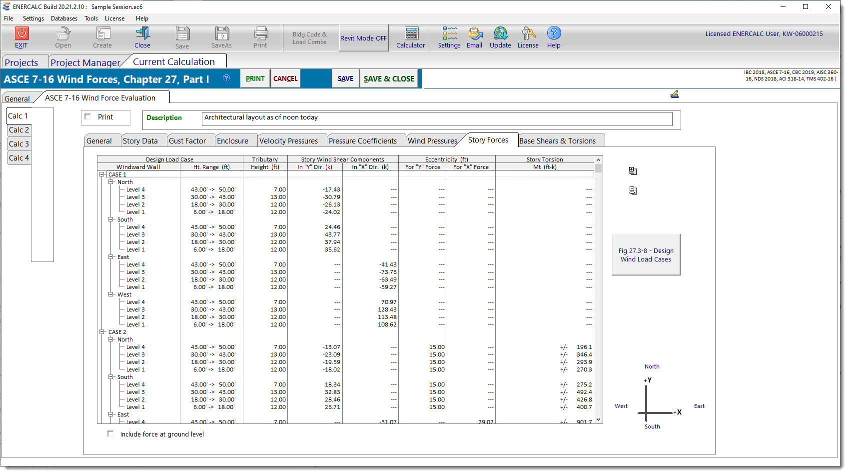
Using the story heights determined on the Story Data tab, the Story Forces tab determines the tributary heights for each floor by assuming a simply-supported wall construction that spans between adjacent floor/roof levels. Wind pressures are applied to the tributary heights and multiplied by the perpendicular dimension of the building to arrive at forces for each story.
The option is provided to either display or hide the forces tributary to the lower half of the lowest level. In some construction types, this component of load is delivered to a slab on grade and is not a design consideration for the Main Wind Force Resisting System.
The program reports results for each of the four "Cases" as presented by Figure 27.4-8 of ASCE 7-10 (Figure 27.3-8 of ASCE 7-16). Cases 2 and 4 also incorporate a design torsional moment as defined in the figure. In all situations, the program reports the force magnitude. In situations where a torsional moment applies, the program reports the moment arm that is being considered for each component of force, as well as the resulting net moment.
The final item in the results on this tab is based on the minimum required wind loads per Section 27.4.7 of ASCE 7-10 (Section 27.1.5 of ASCE 7-16). That section requires that the wind load to be used in the design of the Main Wind Force Resisting System for an enclosed or partially enclosed building shall not be less than 16 psf multiplied by the wall area of the building (and 8 psf multiplied by the roof area of the building projected onto a vertical plane normal to the assumed wind direction). So in this last item in the results list, the program reports story forces assuming 16 psf applied to each wall of the building. As of build 6.12.4.24, the program does not collect enough information to consider the 8 psf on the projection of the roof area, so this additional load may need to be considered with supplemental hand calculations on buildings with other than flat or low-slope roofs.
Base Shears & Torsions
This tab reports the summation of the wind story forces and torsions for all levels in the building, for all four "Cases" and for the minimum required wind loads per Section 27.4.7.
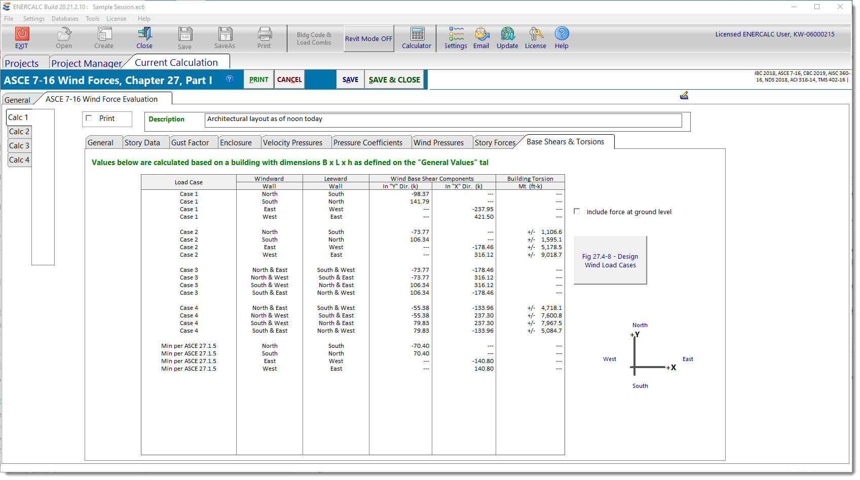
Although "Base Shears" are not technically a part of the ASCE 7 design procedure for wind loads, the summation of all story forces is often of interest to designers for a variety of reasons. Some designers like to see how the wind "base shear" compares to the seismic base shear. For some designers, the summation of the wind forces is useful in the checking process to get a confidence level that the calculated pressures are reasonable. Whatever the reason, the values are reported on this tab if they are of interest.
As with the Story Forces tab, the Base Shears & Torsions tab provides the option to either include or exclude the component of shear and torsion that is tributary to the bottom half of the lowest level.
 <
<