|
Bolt Group |

|

|

|

|

|
|
|
Bolt Group |
|
|
|
|

|
Bolt Group
|
Bolt Group |
|
|
|
|
|
|
|
Bolt Group |
|
|
|
|
|
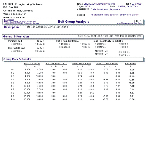
This program provides force distribution from loads applied to a group of up to 16 bolts.
The user enters a vertical and horizontal loads and its location from a datum point. Also with respect to a datum point, the coordinates of up to sixteen bolts are entered.
Using these force and bolt coordinates, the program calculates direct shears and torsional shears on each bolt due to their relative location within the group.
Basic Usage
Vertical and Horizontal Loads and locations are entered after locating a Datum point from which the loads and all bolt locations will be referenced.
Location of Each Bolt is entered starting from the top row in the table, and working downward.
Note!! The last entry in the table that has a (0,0) bolt location is used to tell the program where the last bolt was entered. If any of your bolt locations is (0,0), ENTER THAT BOLT ON THE FIRST ROW OF THE TABLE.
Assumptions & Limitations
| • | When determining the actual load per bolt, at least one load, (either vertical or horizontal) must be specified, otherwise output will be 0". |
| • | At least two bolts should be specified. |
| • | All bolts are assumed to be of the same deformation characteristics when loads are distributed. |
| • | Vertical and Horizontal forces are divided by the number of fasteners to give direct shears. |
Example
The data entry for this example is shown in the screen captures that accompany the Data Entry Tabs and Results & Graphics Tabs sections to follow.
Data Entry Tabs
This set of tabs provides entries for all input in this calculation. While you are entering data and switching between these tabs you can view the desired resulting information on the tabs on the right-hand side of the screen (calculated values, sketches, diagrams, etc.). A recalculation is performed after any entry data is changed. After each data entry you can view the results on the right-hand set of tabs.
General Tab
Eccentric Loads
These loads will be applied to the bolt group. If the actual load is at an angle to the coordinate axis you are using, be sure to resolve it into its vertical and horizontal components.
Eccentricity From Datum
Enter the X or Y coordinate of the point of application of the load according to your X-Y axis system.
Center of Bolt Group (CBG) Location
The program calculates the center of the bolt group you've specified and displays it here. The distances are referenced to the coordinate axis datum being used, and is calculated using statics.
Load Eccentricity from CBG
These values are the distance of the applied load to the center of the bolt group.
Eccentric Moments
This is the actual moment about the calculated Center of Bolt Group. This moment is equal to the vertical or horizontal load, multiplied by the Load Eccentricity.
Bolt Locations Tab
This tab contains the entry areas for the bolt locations. All locations should be entered with reference to a datum point you selected.
Results & Graphics Tabs
This set of tabs provides the calculated values resulting from your input on the "Data Entry Tabs". Because a recalculation is performed with each data entry, the information on these tabs always reflects the accurate and current results, problem sketch, or stress/deflection diagram.
Bolt Calculations Tab
Bolt Dist. from Center of Bolt Group
From the user defined bolt location and the calculated center of bolt group, the distance from bolt to center of bolt group is found. If the bolt is to the left or above the C.B.G., it will be displayed negative, and vice versa.
Direct Shears
The direct shear to each bolt is simply the applied vertical or horizontal load divided by the total number of bolts.
Torsional Shears
The torsional shears are calculated considering the actual bolt location with the C.B.G.
The following relationship is used:
Torsion = Applied Load * Arm
-also-
SUM ( Bolt Force * Bolt Dist to C.B.G. )= SUM ( di * Fi )
Where:
di=Absolute distance from bolt to C.B.G.
Fi =Absolute Force on each bolt.
Setting: Fi= Alpha * di
We get: Pe=SUM ( Alpha * di 2 )
Then: Alpha=P * e / SUM ( di 2 )
But : di^2 = ( X-Dist to CBG)^2 + ( Y-Dist to CBG )^2
From the above relationship, we can easily calculate Alpha.
Therefore, Fi = Alpha * di
Resultant Bolt Force
This is simply the resultant of the direct and torsional shear components for each bolt, added vectorially to determine the maximum load per bolt.
Sketch Tab
This tab provides a sketch of the beam with loads and resulting values shown. Using the [Print Sketch] button will print the sketch in large scale on a single sheet of paper.
Sample Printout