|
Base Plate |

|

|

|

|

|
|
|
Base Plate |
|
|
|
|

|
Base Plate
|
Base Plate |
|
|
|
|
|
|
|
Base Plate |
|
|
|
|
|
This program performs column base plate design for W, S, or HP sections. The designer can :
| • | For a selected base plate size, axial load, and column, the required base plate thickness is determined. |
| • | Determine base plate dimensions and thickness for a given column and axial load per AISC. |
This program follows the design procedure detailed in the AISC specification as an absolute minimum plate thickness, and provides an extended plate analysis when moments are applied to the plate.
Both axial loads and moments about the X-X axis of the column can be applied. The analysis procedure checks for different resultant force locations, and uses an appropriate analysis technique considering anchor bolt location, plate thickness, column flange and web dimensions, and concrete strengths.
Basic Usage
| • | This program can either calculate the required thickness of a baseplate using the design criteria or you can enter the thickness and have plate and bearing stresses determined. |
| • | Bolt Data specifies the tension capacity of the anchor bolts, number of bolts per side of the column, the area of each bolt, and distance of the bolts from the edge of the base plate. These values will be used to define the base plate geometry to determine resultant force zones in the analysis. |
| • | Baseplate and Pier Dimensions are needed to determine bearing area and area ratios for determining allowable concrete bearing stress. |
| • | Material Strengths to be entered include Fy of column, f'c of supporting concrete, and load duration factor to use (which would indicate that the applied axial load and moment is due to seismic, wind, or other short term event). |
| • | Reviewing Forces and Stresses. In the "Summary section of the worksheet the actual and allowable bending and shear stresses will be listed. Also, various moments, shears, deflections and reactions due to six load placement conditions will be given. |
Unique Features
This program provides a thorough analysis of the iteration of plate and bearing surface. Four separate zones are define depending upon the position of the force resultant in relation to the plate, bolt, and column dimensions for use in calculating stresses.
Assumptions & Limitations
| • | The program offers both ground up design of the base plate size and thickness, or just thickness determination based upon user specified overall plate dimensions. |
| • | The allowable bearing stress on concrete is calculated based upon an allowable increase using on the ratio of plate and concrete areas. |
Steel Section Database
Built into the software is a complete database of common rolled sections available from various mills in the United States. On each tab labeled #1, #2, etc. there will be a button that looks like this:
![]()
This button displays the steel section database as shown below.
On this window there are various controls and options.....
Steel Database : Allows you to select between several common shapes databases.
Section Type to Display: Allows you to select which steel section designation to display in the list. These shapes conform to the American Institute of Steel Construction shape designations. To make your selection simply move the mouse over the letter(s) and when the highlight activates left-click once with your left mouse button.
Depth Range: This item allows you to specify depth limits to be used for selecting which sections to display in the list. When the checkbox to the left is not checked the selection wording and entries will not appear and all sections will be displayed. These dimensions are compared to the "Depth" dimension of the sections.
Class Range : This item allows you to specify the limits in "Depth Class" to be displayed in the table. The "Depth Class" of a section is the first numeric number in the sections name. For instance a wide flange W14x22 is in depth class "14". a channel C9x15 is in depth class "9", and a L5x3x1/4 is in depth class "5".
Equal & Unequal Legs : These two buttons appear when you have selected section type "L" which are single angles. The limit the display of the list to angle with equal dimension or unequal dimension sides.
Equal Legs, Long Leg Vertical, Short Leg Vertical: These three buttons appear when you have chosen to display section type "LL". These control the display of sections between pairs of angles with both sides of equal length, of unequal side length angles paired with the LONG side together, and unequal side length angles paired with the SHORTside together.
Square & Rectangular Tubes: These two buttons appear when you have chosen section types TS or HSS-T. These are square tubular sections. You can choose to display only square tubes or alternately tubes with unequal sides.
Sort Tabs for Database Table : Immediate above the database list of sections you will see tabs looking like this....
When selected each tab will sort the list in the order described by the text on that tab.
Sort order : These two buttons allow you to chose the list order of the sections. The sorting order will be according to the sort tab selected and shall be in ascending or descending order.
Database Table Itself : The main area on the window will be where the steel sections are displayed as a result of all of your choices as described above.
[Select] : This button is displayed when you have clicked on the [Section] button when you press [Select] the section in the list that is currently highlighted will be selected and the name and data brought into your calculation.
[Insert]: Use this button to add a steel section to the database. When pressed you will see the following window:
The only really important item to enter is the "Type" item. This specifies what standard rolled section type your section is. This item is used internally by the program to decide which stress analysis method to use for determining the sections allowable stress, how to consider unstiffenned elements, and many other code checking items.
[Change]: Will display the same window as above but allow you to change section properties.
[Delete] : Will enable you to delete sections. Note: No sections in the supplied database can be deleted. Only Sections that you ad can be later deleted.
[Cancel]: Exit the steel database window.
ASD & LRFD Design Modes
Allowable Stress Design and Load & Resistance Factor Design as specified by the American Institute of Steel Construction is provided by this program. Only screen captures and descriptions for ASD are presented in this book. More detailed LRFD documentation will be added and will be available in the electronically delivered versions of this book. Check these locations for electronic media:
| • | Latest Adobe Acrobat PDF documentation file here: ftp://208.36.30.226/sel5.pdf. |
| • | Latest Windows Help system file here : ftp://208.36.30.226/enercalc.hlp. |
| • | Internet HTML help documentation presented as web pages at www.enercalc.com/sel_help. |
Example
The data entry for this example is shown in the screen captures that accompany the Data Entry Tabs and Results & Graphics Tabs sections to follow.
Data Entry Tabs
This set of tabs provides entries for all input in this calculation. While you are entering data and switching between these tabs you can view the desired resulting information on the tabs on the right-hand side of the screen (calculated values, sketches, diagrams, etc.). A recalculation is performed after any entry data is changed. After each data entry you can view the results on the right-hand set of tabs.
General Tab
Axial Load
Vertical load applied to the base plate.
X-X Axis Moment
Moment applied to the baseplate via the column. Please note that only major axis bending is allowed.
Plate Height & Width
This item changes it's visible display depending on the "Usage Mode" specified on the tab at the bottom of the screen.
If usage mode is "Determine Size & Thickness" or "Determine Thickness Only" this item is not an entry....is it displayed as the calculated minimum plate height and width to satisfy stress limits.
If usage mode is "Check Plate for Plate Size Entered & Loading" then these items are shown as entries for you to specify the sizes.
"Height" dimension is measured along the Y-Y axis of the column. "Width" dimension is measured along the X-X axis of the column.
Plate Thickness
This item changes it's visible display depending on the "Usage Mode" specified on the tab at the bottom of the screen.
If usage mode is "Determine Size & Thickness" or "Determine Thickness Only" this item is not an entry....is it displayed as the calculated minimum thickness to satisfy stress limits.
If usage mode is "Check Plate for Plate Size Entered & Loading" then this item is shown as an entry for you to specify the plate thickness.
Pier Height
Pier dimension measured along the Y-Y axis of the column.
Pier Width
Pier dimension measured along the X-X axis of the column.
Steel Section
This is the steel section name that you have specified, either by typing in the name and using the database search abilities (see above)
Usage Mode Tab
Select how the program should work :
| • | Determine Size & Thickness calculates the minimum required plate size and thickness to satisfy stress requirements using the loads, pier dimensions, bolt data and column size data. |
| • | Determine Thickness Only calculates the minimum requires plate thickness to satisfy stress requirements using the loads, plate dimensions, pier dimensions, bolt data and column size data. |
| • | Check Stresses for Plate Size & Load uses your entered plate height, width and thickness along with all other entered data and calculates the stresses. |
Anchor Bolt Tab
Dist. From Plate Edge
Distance from the plate edge to the centerline of the anchor bolt.
Bolt Count Per Side
Number of bolts on each side of the column.
Tension Capacity
Tension capacity of one anchor bolt.
Bolt Area
Area of each anchor bolt.
Steel Shape Data Tab
This tab shows the dimensions of the selected steel section.
Allowable Stresses Tab
f'c
Allowable concrete compressive stress for support of the baseplate.
Fy
Allowable yield stress for steel baseplate.
Load Duration Factor
Allowable stress increase factor to be applied to steel and concrete stresses for determining allowable stresses.
Results & Graphics Tabs
This set of tabs provides the calculated values resulting from your input on the "Data Entry Tabs". Because a recalculation is performed with each data entry, the information on these tabs always reflects the accurate and current results, problem sketch, or stress/deflection diagram.
Results Tab
Actual Bearing Stress
Maximum bearing stress under the baseplate at the edge where axial load and compressive force due to bending is combined.
Allow. per ACI 318-02, A3.1
Absolute maximum baseplate capacity for the calculated maximum allowable bearing stress.
Allow per AISC J9
Maximum allowable concrete bearing stress considering load duration factor and ratio of pier area to baseplate area.
Actual fb
Actual bending stress in the plate.
Maximum Allowable Plate Fb
Allowable bending stress in plate.
Actual Bolt Tension
Calculated tension in anchor bolt on one side of the plate when a moment is present and there is tension forces in the anchor bolts.
Allowable Bolt Tension
Entered allowable bolt tension * Load Duration Factor
Sketch Tab
This tab provides a sketch of the beam with loads and resulting values shown. Using the [Print Sketch] button will print the sketch in large scale on a single sheet of paper.
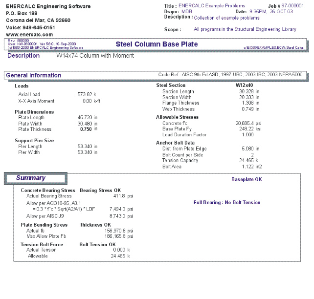
Sample Printout