Deflection Results |
  
|
Deflection Results |
|
It is important to understand that on the Summary Results tab of any of the beam modules, the program reports the conditions that produce the controlling deflection ratios...not necessarily the maximum deflection values.
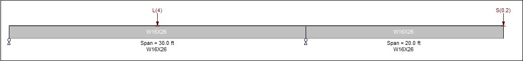
To understand the significance of this distinction, consider the following beam with a cantilever:

And let's assume the loading looks like this:
The program is going to do the following:
1.Perform a structural analysis of the beam for each primary load case (dead load, live load, snow load, etc.).
2.Determine deflections for each load case at many small increments along the length of the beam.
3.Combine the deflections at each small increment in the proportions dictated by the load factors in the service load combinations.
4.Determine the maximum upward and downward deflections for each span in the beam.
5.Calculate a resulting ratio for each span in the beam by dividing the span length by the maximum upward and downward deflections for that span.
6.Report (on the Summary Results tab) the conditions that produce the controlling ratio for:
•Maximum downward deflection based on live loads only
•Maximum upward deflection based on live loads only
•Maximum downward deflection based on total load
•Maximum upward deflection based on total load
One other detail that is important to keep in mind is that for cantilevers it is customary to calculate the deflection ratio by dividing twice the span length by the deflection.
Now that we've established what actually happens to produce deflection results, here are the results for the beam indicated above:
Span |
1 |
2 |
|---|---|---|
Length |
360 inches |
240 inches |
Maximum Downward Deflection |
0.447 inches due to D+L |
0.457 inches due to D+S |
Ratio |
360/0.447 = 805 |
2x240/0.457 = 1050 |
Notice that the overall maximum downward deflection occurs in Span 2 (at the free end of the cantilever) and is 0.457 inches due to dead plus snow loads. However, the controlling ratio is actually produced in Span 1, which experiences a slightly smaller deflection magnitude. Therefore the program would report on Span 1 in the Summary Results tab. This is a good example of how these deflection values can produce some interesting results. It also illustrates the important distinction between controlling deflections and controlling deflection ratios. If it is absolute deflections that are of concern in your design, then you can study them on the Service Load Deflections tab on the M-V-D Summary tab.
