Assigning Proper Fixities |
  
|
Assigning Proper Fixities |
|
When working with truss models with pinned joints, consider setting the Joint Fixity (Boundary Restraints) to Free – Free – Fixed for typical joints, and setting the Member Fixity (End Conditions) to Fixed – Fixed – Pinned. This ensures that members are hinged at the joints, and it is the easiest way to achieve stability.
To model pinned supports you can set the Joint Fixity to Fixed – Fixed – Fixed at nodes that represent supports. Even though the support joints are modeled as Fixed against rotation, all members framing into those joints already have their Mz degree of freedom released at both ends, so no moment will be delivered to the supports from the members.
There must be at least two "support joints" to create global stability of the entire truss. Typically we see two support joints with "Y" fixity and one support joint with "X" fixity, but many conditions are possible.
When working with portal frames with moment connected joints, consider setting the Joint Fixity (Boundary Restraints) to Free – Free – Free for typical joints, and setting the Member Fixity (End Conditions) to Fixed – Fixed – Fixed. This ensures that members are continuous through the joints, and it is the easiest way to achieve stability.
Finally, to model fixed bases you can set the Joint Fixity to Fixed – Fixed – Fixed at nodes that represent supports.
When working with portal frames with moment connected joints, consider setting the Joint Fixity (Boundary Restraints) to Free – Free – Free for typical joints, and setting the Member Fixity (End Conditions) to Fixed – Fixed – Fixed. This ensures that members are continuous through the joints, and it is the easiest way to achieve stability.
Finally, to model pinned bases you can set the Joint Fixity to Fixed – Fixed – Free at nodes that represent supports.
When working with models with a mix of fixity conditions, consider setting the Joint Fixity (Boundary Restraints) to Free – Free – Free for typical joints, and setting the Member Fixity (End Conditions) to Fixed – Fixed – Pinned for typical members. Then it becomes necessary to modify the Member Fixity (End Conditions) to Fixed – Fixed – Fixed for members that are to be modeled as continuous.
The next step is to achieve stability. This requires that you review the model and identify any conditions where Free – Free – Free joints are NOT already rigidly connected to at least one member by a fixed Mz End Condition. If any of these nodes are found, they must be stabilized by providing at least one fixed Mz End Condition. Use caution when performing this process. If more than one member is fixed to a joint, then continuity develops at that location, and it no longer behaves as a fully pinned joint. Remember...in a fully hinged Free – Free – Free joint, only one member must be rigidly connected to the joint with a fixed Mz member end condition to achieve stability while still maintaining the fully-hinged behavior at that joint.
Finally, you must focus on the support nodes. If pinned supports are desired, you will use either a Fixed – Fixed – Fixed or a Fixed – Fixed – Free Joint Fixity (Boundary Restraint) at support nodes. The choice of Mz Fixed or Mz Free for support nodes depends on the member end conditions of the members framing into the joint. If exactly one member end at a support node has a fixed Mz condition, then the support nodes should be modeled as Fixed – Fixed – Free in order to behave as a pinned support. If all member ends at a support node have pinned Mz condition, then the support nodes should be modeled as Fixed – Fixed – Fixed in order to achieve stability for the node and still behave as a pinned support. If fixed supports are desired, you will use a Fixed – Fixed – Fixed Joint Fixity (Boundary Restraint) at support nodes. Just make sure that the appropriate member ends are modeled with Mz fixity in order for those members to be able to transfer moment to the fixed bases.
At present there is no explicit method of defining a base with partial moment fixity, but it can still be modeled with a little creativity. Consider modeling something like the concept shown below:
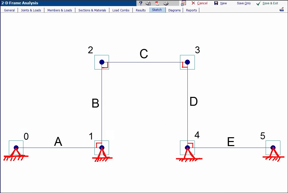
In this model, members A and E are fictitious members that are only there for the purpose of providing partial moment fixity at the bottoms of members B and D. With this concept, it would be possible to experiment with the section and the member length for members A and E to achieve the desired rotational stiffness at joints 1 and 4.
