> For the complete documentation index, see [llms.txt](https://enercalc.com/docs/llms.txt). Markdown versions of documentation pages are available by appending `.md` to page URLs; this page is available as [Markdown](https://enercalc.com/docs/sel-user-manual/calculation-modules/beams.md).
# Beams
Overview of the single- and multi-span steel, concrete, and wood beam design module in ENERCALC SEL.
## Overview
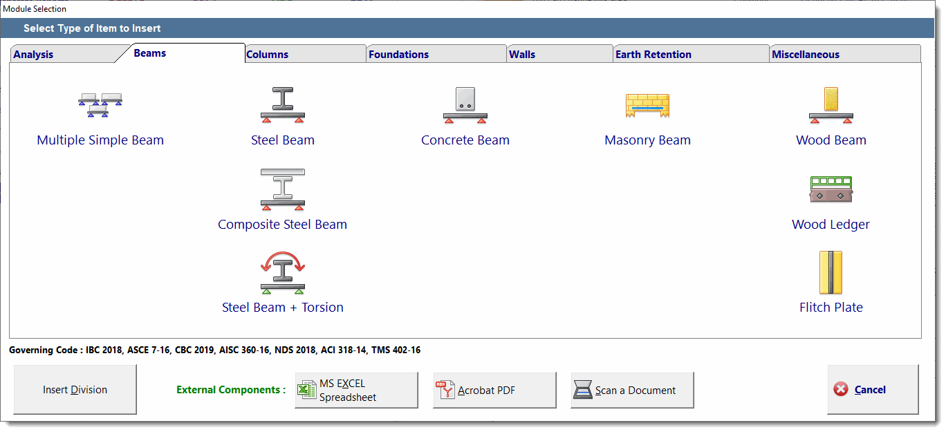
There is one main module for designing Steel, Concrete and Wood beams. There are separate modules for Composite Steel Beams, Steel Beams with Torsional Loads, and one for Masonry Lintels.
This section deals ONLY with typical single- or multi-span Steel, Concrete & Wood beams.
The presentation screen is divided into three areas: **Beam representation & modification**, **Data Entry** & **Calculation Results** as illustrated in the screen capture below:
Beam module presentation screen
**(1) Beam representation & modification:** This area allows you to create and modify the beam layout.
Click on the support icons  to select the type of support fixity: Fixed, Pinned, or Free.
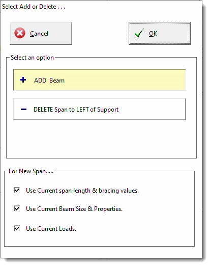
Click on the \[**+/-**] icon  to display a window to add or delete beam spans:
Click on the beam representation to change the beam specific data on the **Beam Span Data** and **Span Loads** tabs.


**(2) Data Entry:** This set of tabs is where you enter all information for the beam. These tabs will show different information according to material type selected. See the specific chapters for the items provided for each material. Click one of the following to jump: [Wood](/docs/sel-user-manual/calculation-modules/beams/woodbeam.md) [Steel](/docs/sel-user-manual/calculation-modules/beams/steel-beam.md) [Concrete](/docs/sel-user-manual/calculation-modules/beams/concretebeam.md)
Here is a summary of the purpose of each tab:
## General

### **Beam Material**
Clicking one of these buttons changes the material type used for the beam.
**Compression Edge Lateral Bracing** These selections control how the module will evaluate the lateral compression edge bracing for the design. When **Define Bracing Span-by-Span** is selected, the unbraced length is defined on a span-by-span basis on the Beam Span Data tab. When any of the other options are selected, the unbraced length is defined here on the General tab, and that definition is applied to all spans of the beam.
### **Design Method**
For wood & steel you can select ASD or LRFD design methods. Concrete design is always ultimate strength (LRFD).
### **Design Values**
Specify material-specific design values.
## Beam Span Data
This tab is used to define span length and beam section information:

### **Select Span**
These buttons allow you to select which span the values in the data entry area apply to.
### **Span Length**
This is where you define the length of the currently selected span.
### **Deflection Ratios**
These are used as the basis for the deflection design check and also as the starting point for automatic member selection.
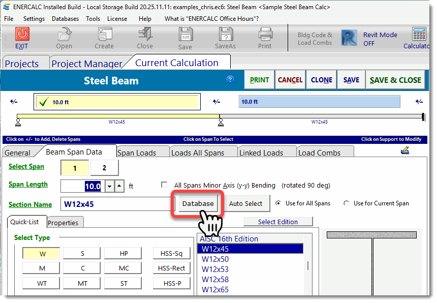
**Section Name & Buttons** For steel and wood you can enter the standard beam section designation. You can also type in the section name and the module will search the built-in database for a match. If a match is found, the section properties will be loaded from the database and they will appear on the Properties tab.
Click the button indicated below to open the section database for rolled steel shapes:
Open the steel shape database
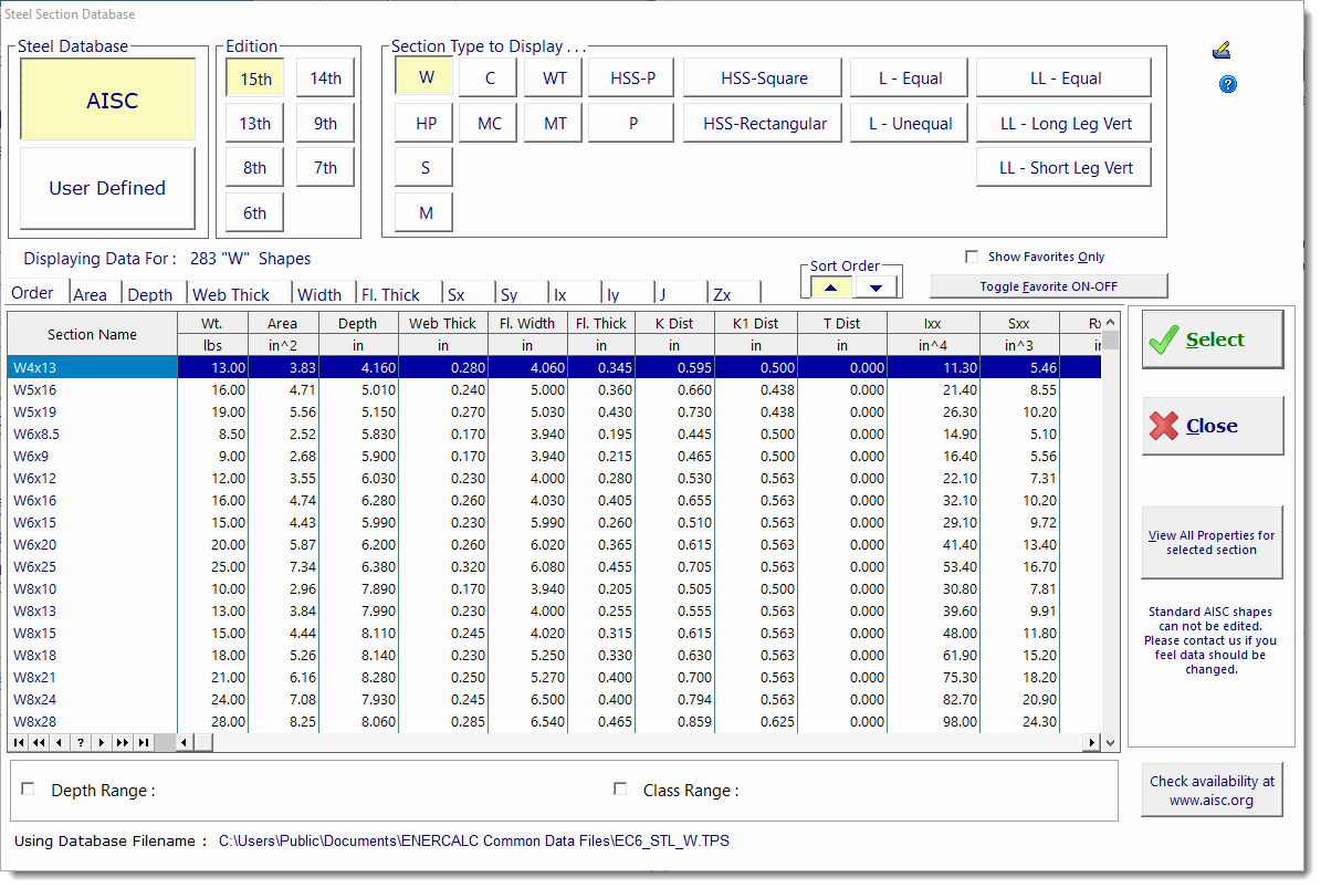
The database contains an extensive number of standard shapes commonly used in the USA.
Steel shape database
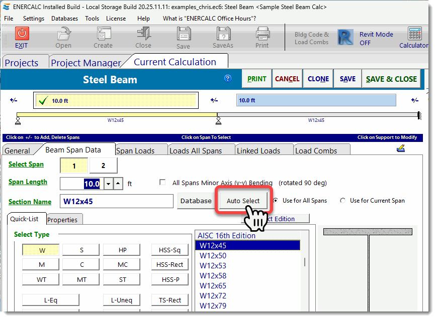
Click the button indicated below to display the Steel Member Design dialog:
Open Steel Member Design
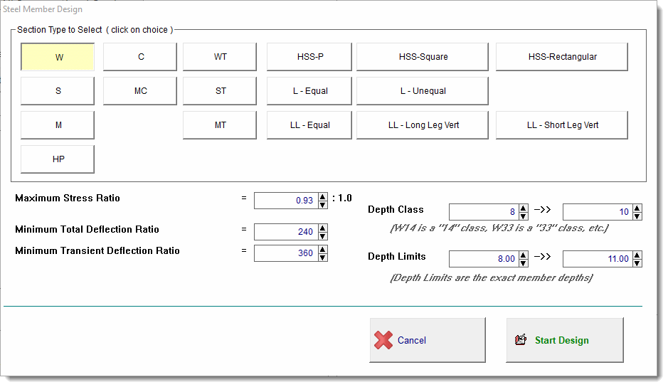
This provides control over the type of member to be selected and various stress ratio, deflection ratio and size limits to respect during the automatic member selection process.
Steel Member Design settings
The Quick-List provides a fast way to select a member section from the database. Just select the desired edition of the database, click the type of member, scroll through the list and click on your selection.

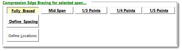
**Compression Edge Lateral Bracing** When you have selected Define Bracing Span-by-Span on the General tab you will see the following bracing options on the Beam Span Data tab:
Compression-edge lateral bracing options
These selections control how the module will evaluate the lateral compression edge bracing for the beam span selected above.
The top row has common selections for fully-braced conditions as well as options to divide the selected span into segments of equal braced length.
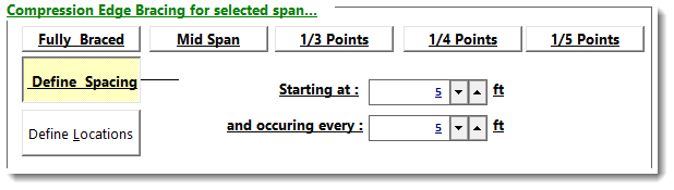
The Define Spacing option lets you set a starting point and subsequent spacing for the bracing within the selected span:
Define bracing spacing
The Define Locations option lets you set up to three specific bracing locations referenced from the left end of the selected span:

## Span Loads
This tab is used to specify loads **FOR THE SELECTED SPAN ONLY** (except as noted below) using the tools shown on the following screen capture:

Use the \[**Add Load**], \[**Copy Load**] and \[**Delete Load**] buttons to add, copy, or delete loads on the selected span.
Use the **Load Type** selections to specify the type of load that will be added. This selection affects the **currently highlighted** item in the table of loads. The data entry areas below will change based on the type of load selected.
The **Auto Add Beam Weight** option will calculate the weight of the beam and add it to your applied loads as a uniform dead load on the beam. Note that this option applies to the FULL LENGTH of the beam...it is NOT a setting that can be set on a span-by-span basis.
The **Auto Unbalanced Live Load Placement** option is a very powerful selection. When you have two or more spans, you can select this item and the module will automatically generate load combinations for all possible permutations of patterned live load being placed on alternate spans. For instance, on a two-span beam, it would create conditions that place live load on both spans, live load on the left span only, and live load on the right span only. That is a total of three permutations of live load, and it will do this for ALL of the load combinations that are selected to run.
{% hint style="warning" %}
**NOTE:** **This can significantly increase recalculation time needed for beams with many spans.**
{% endhint %}
**Load classifications are**: D: Dead, Lr: Roof Live, L: Live, S: Snow, W: Wind, E: Seismic, H: Earth Pressure
**Loads that get patterned with this feature**: Lr: Roof Live, L: Live
## Loads All Spans
This tab offers tools that are used to specify loads with spacings or lengths that might cause them to overlap multiple spans as shown in the screen capture below:

Click the load type button on the left and the appropriate load entry items will appear to allow you to define the magnitude, location and extent of the load. With all load items set to \[**None**], the tab will be almost entirely blank.
**Start Dist** and **End Dist** defines the application distance from the **FAR LEFT** end of the beam. For a beam with two 20' spans where you want to apply a uniform load 5' in from each end use Start Dist = 5.00 and End Dist = 35.00.
The third item allows you to define repeating point loads or moments. You define the position of the first load and the spacing increment thereafter.
The last item allows you to define repeating loads on EACH span. Load specification is for the load in EACH span. For example, consider a two-span beam where the first span is 25' and the second span is 45'. Selecting \[**1/3 Points**] will place loads at 8.33', 16.66' from the left support of the first span and at 15' and 30' from the left support of the second span. The "Specify" option allows you to provide a unique spacing **measured from the left end of each span**.
Although this tab is not typically used for single-span beams, the tools are perfectly applicable to single-span beams.
## Linked Loads
This tab is used to dynamically transfer support reactions from other calculations and apply them as loads on the current beam calculation, allowing you to maintain a connected load path.
For more information on using Linked Loads, see [Linked Loads Overview](/docs/sel-user-manual/calculation-modules/linked-loads/linked-loads-overview.md).
Linked Loads tab
## Load Combinations
This tab is used to specify the load combinations that will be run for the analysis of this beam, as shown in the screen capture below:

The **\[Select]** button is used to retrieve load combinations sets from the [Load Combination](/docs/sel-user-manual/main-menu/databases-in-main-menu/load-combination-manager.md) database.
The icon with the delta symbol is used to edit the load combination values. Click on the delta symbol, and the multipliers for the currently selected load combination can be revised. After you change an item's values, click OK to save the change and view the revised load combination in the list.
Specify the magnitude of SDS and/or Rho to automatically integrate the associated additional internal factor in the load combinations.
The option labeled \[**Automatically create combination using opposite sign for**] triggers the module to create **additional** load combinations with the "**W**" and/or "**E**" factors set to negative values. This has the effect of reversing the direction of application of the wind and seismic loads that have been applied to the member.
**(3) Calculation Result:** This set of tabs at the top of the right side of the screen allows you to select the desired results for review:

**Calculations** provides several tabs that let you review the numeric detail of the calculation. The left-most tab is always the Summary Results where the concise design is given.

See the individual sections for each material type for specific discussions of these result sections.
**2D** provides a scale illustration of the item you are designing, including an indication of support conditions and applied load magnitudes.

**Diagram** provides a moment, shear, or deflection diagram for the item you are designing.

**3D** displays a 3D rendering of the item you are designing, including an indication of support conditions, bracing and applied load magnitudes.

---
# Agent Instructions
This documentation is published with GitBook. GitBook is the documentation platform designed so that both humans and AI agents can read, navigate, and reason over technical content effectively. Learn more at gitbook.com.
## Querying This Documentation
If you need additional information that is not directly available in this page, you can query the documentation dynamically by asking a question.
Perform an HTTP GET request on the current page URL with the `ask` query parameter, and the optional `goal` query parameter:
```
GET https://enercalc.com/docs/sel-user-manual/calculation-modules/beams.md?ask=&goal=
```
`ask` is the immediate question: it should be specific, self-contained, and written in natural language.
`goal` is optional and describes the broader end goal you are ultimately trying to accomplish on behalf of the user. GitBook uses it to tailor the answer towards what is most useful for that goal.
The response will contain a direct answer to the question and relevant excerpts and sources from the documentation.
Use this mechanism when the answer is not explicitly present in the current page, you need clarification or additional context, or you want to retrieve related documentation sections.
.png?alt=media)
.png?alt=media)